🔷Calculate Point Cloud Bounding Box
Function Description
This operator calculates three-dimensional bounding boxes for each input point cloud and outputs the geometric information of the bounding boxes.
Two types of bounding boxes can be selected:
-
Axis-Aligned Bounding Box (AABB): The faces of the bounding box are parallel to the X, Y, and Z axes of the coordinate system. Simple and fast to calculate, suitable for cases where the object orientation is roughly aligned with coordinate axes.
-
Oriented Bounding Box (OBB): The orientation of the bounding box is determined by the principal directions of the point cloud itself, enabling tighter enclosure of objects with arbitrary orientations.
Usage Scenarios
-
Object size and position estimation: Obtain the three-dimensional dimensions and center position of objects represented by point clouds.
-
Rough pose estimation: OBB can provide object orientation information.
-
Spatial occupancy analysis: Determine the approximate range occupied by objects in space.
-
ROI generation: Quickly generate regions surrounding point clouds for subsequent fine processing.
-
Collision detection: Use simple AABB or tighter OBB for preliminary collision detection.
Input Output
Input |
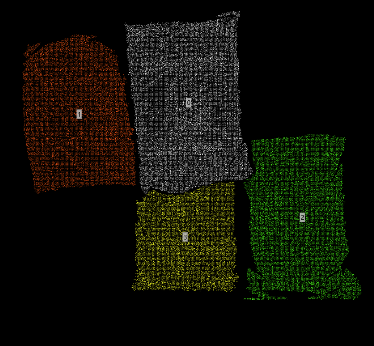
Point Cloud: Input point cloud or list of point clouds. If it’s a list, bounding boxes will be calculated independently for each point cloud in the list. The operator will internally attempt to remove NaN values from point clouds before calculation. |
|
Output |
Bounding Box Normal: List of normal vectors for the calculated bounding boxes. Bounding Box Center: List of center points for each calculated bounding box, calculation method determined by the center point type parameter. Bounding Box: List of detailed information for each bounding box. Bounding Box Size: List of X, Y, Z dimensions of each bounding box along its principal axes. 3D ROI: List of three-dimensional ROIs generated based on calculated bounding boxes, possibly with scaling adjustments. |
|
Parameter Description
|
This operator has two versions:
Both versions have exactly the same core functionality and parameters, differing only in the type of point cloud data they process. |
Calculation Method
Parameter Description |
Select the type of bounding box to calculate. |
|
Parameter Adjustment |
OBB Oriented Minimum Bounding Box (OBB, Default): Calculate the minimum volume bounding box with orientation that tightly encloses the point cloud. Suitable for objects with arbitrary orientations, providing more accurate size and orientation information, but slightly more complex to calculate. |
|
AABB Axis-Aligned Bounding Box (AABB): Calculate the minimum bounding box with faces parallel to coordinate axes that encloses the point cloud. Simple and fast to calculate, but for tilted objects, the dimensions will be larger than the actual object. |
|
|
Choose based on application requirements. If precise object dimensions and orientation are needed, choose OBB; if only approximate range is needed and the object orientation is regular, or faster speed is required, AABB can be selected. |
||
Center Point Type
Parameter Description |
Select how the output "Bounding Box Center" is calculated. |
Parameter Adjustment |
|
Normal Z Direction
Parameter Description |
Specify whether the Z component of the output "Bounding Box Normal" should be positive or negative. The operator will adjust the direction of the calculated normal vector according to this setting. |
Parameter Adjustment |
Used to unify the orientation of output normal vectors. If you want the normal vector to always point towards the positive Z direction ("upward"), select "Positive Z"; if you want it to point towards the negative Z direction ("downward"), select "Negative Z". |
Scaling Method
Parameter Description |
Select how to adjust (scale/expand) the final output 3D ROI region. |
Parameter Adjustment |
|
X/Y/Z Direction Scaling Range
Parameter Description |
Takes effect when "Scaling Method" is set to "Specified Value". Specifies the distance to expand outward (positive values) or shrink inward (negative values) in the X, Y, and Z directions of the bounding box (note: for OBB, this refers to the bounding box’s own coordinate axes). |
Parameter Adjustment |
Used for precise control of ROI size. For example, X=10 means the ROI is 20mm wider than the original bounding box in the bounding box’s own X-axis direction (10mm added on each side). |
Parameter Range |
[-5000, 10000], Default: 0, Unit: mm |
|
|
|
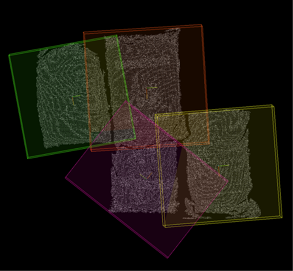
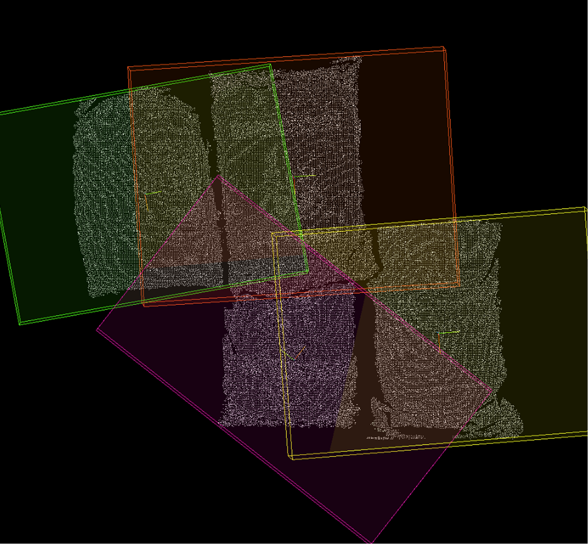
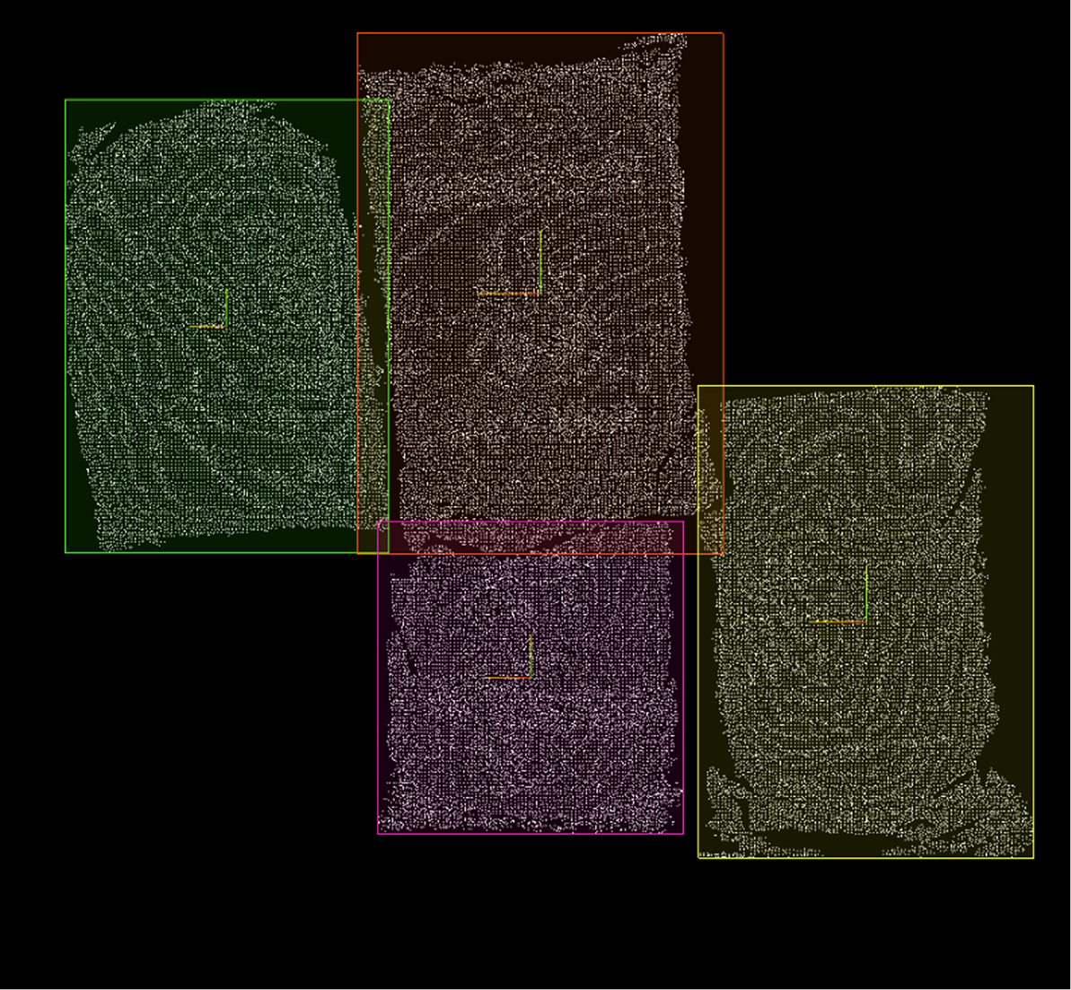
X Direction Scaling Range=0mm |
X Direction Scaling Range=100mm |
X Direction Scaling Range=200mm |
X/Y/Z Direction Scaling Ratio
Parameter Description |
Takes effect when "Scaling Method" is set to "Specified Ratio". Specifies the scaling factor for ROI (and possibly bounding box) in the X, Y, and Z directions (bounding box’s own coordinate axes). |
Parameter Adjustment |
A scaling factor of 1 means maintaining original size, greater than 1 means enlarging, less than 1 means shrinking. For example, x=1.1 means the ROI size in the bounding box’s own X-axis direction becomes 1.1 times the original. |
Parameter Range |
[0, 5], Default: 1 |
|
|
|
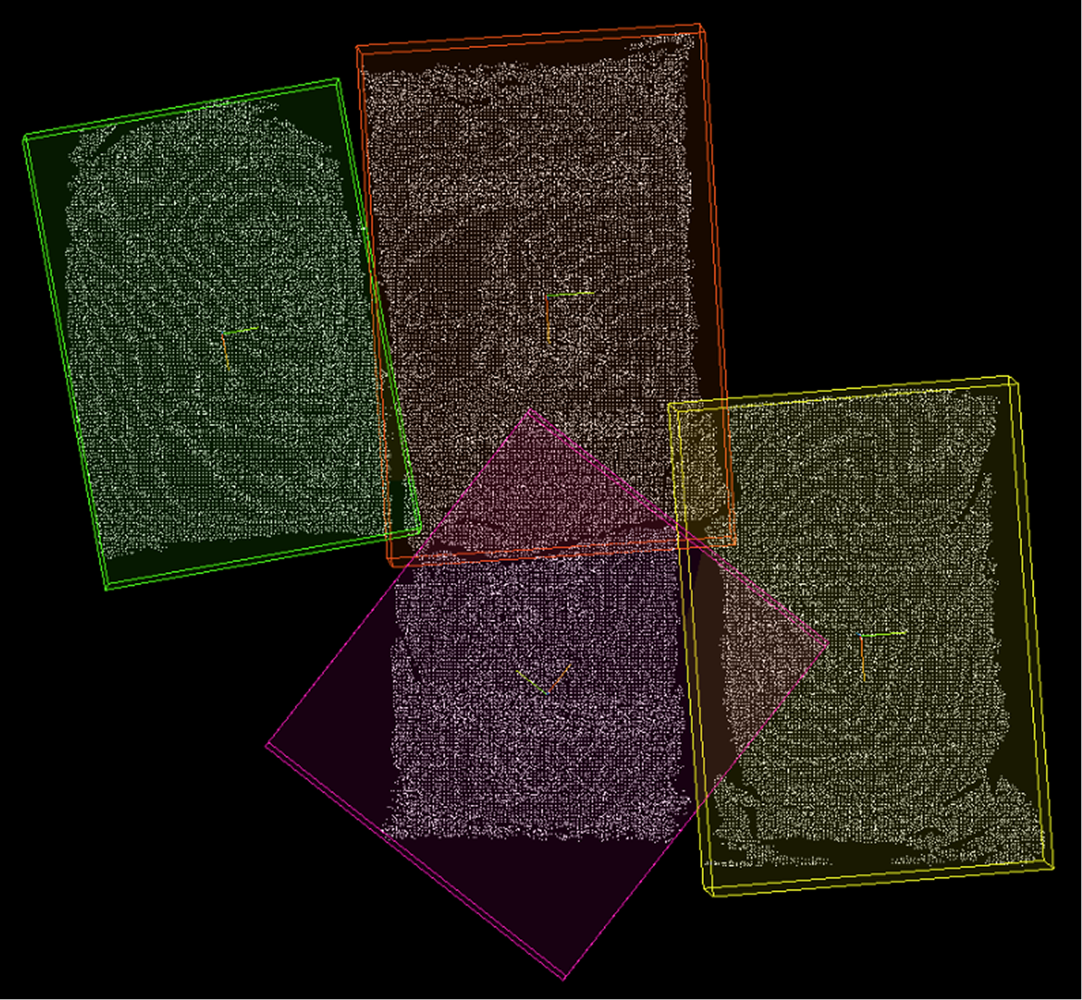
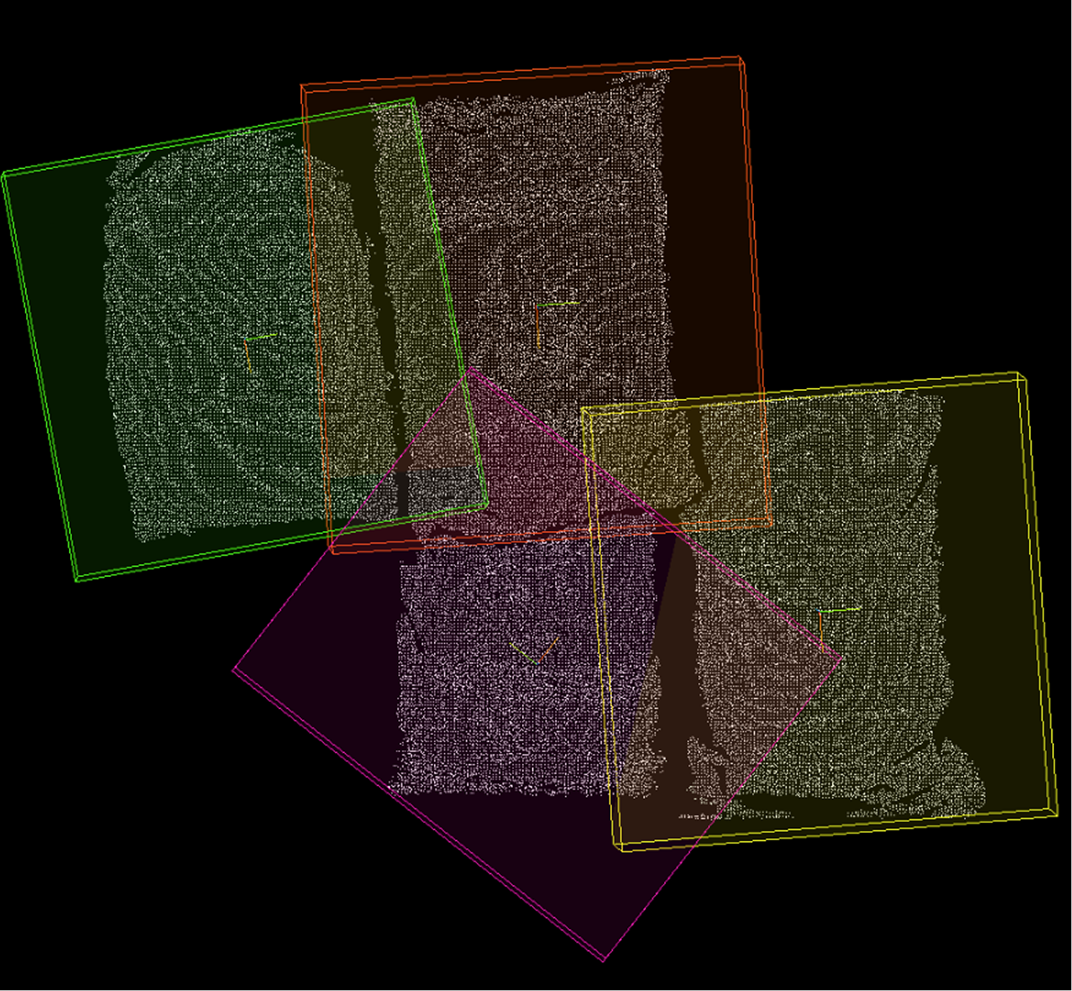
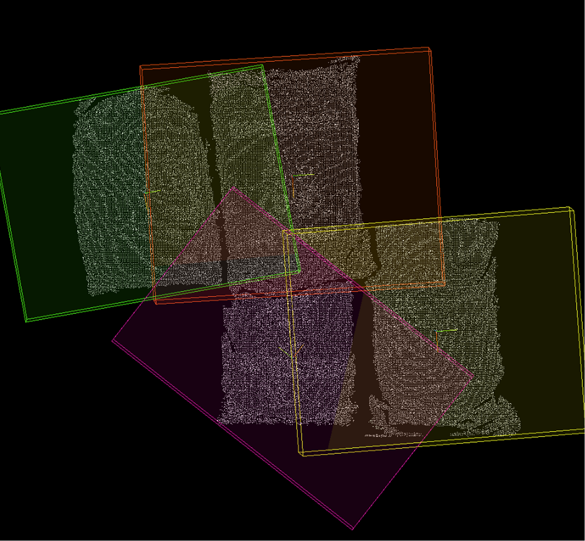
X Direction Scaling Ratio=0 |
X Direction Scaling Ratio=1.5 |
X Direction Scaling Ratio=2 |