🔷Point Cloud Bounding Box (Aligned Along Line)
Function Description
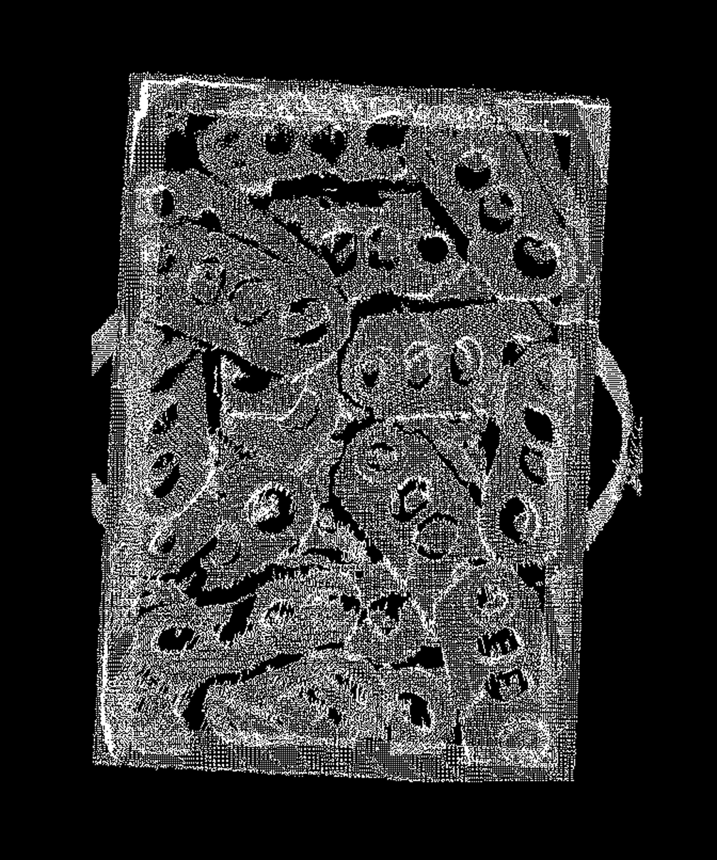
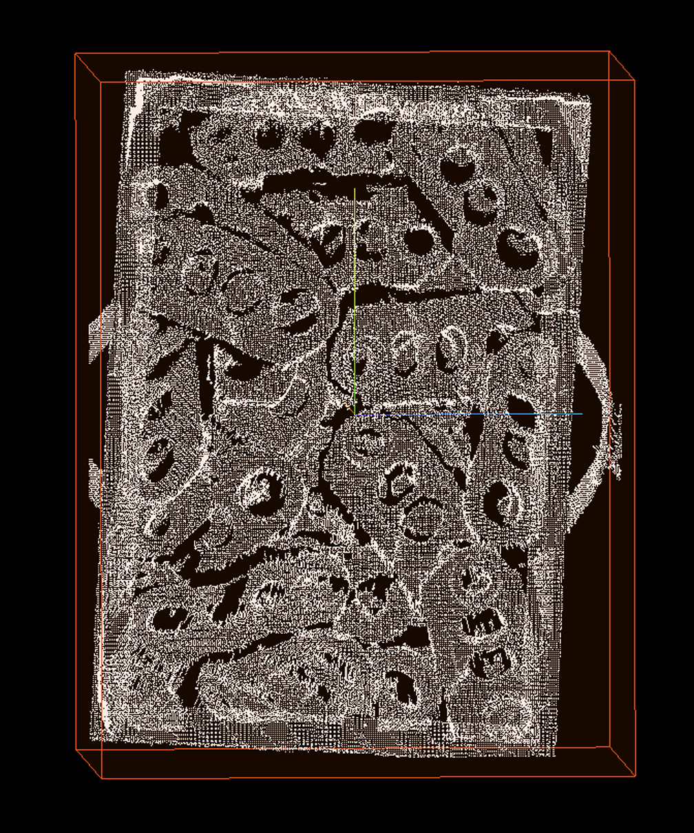
This operator computes an oriented 3D bounding box (OBB) for each input point cloud. Unlike standard OBB computation, this operator forces one of the principal axes of the bounding box (typically the longest axis) to align with the direction of a user-input line, and finally outputs the parameters of this aligned OBB, including center point, dimensions, transformation matrix, normal vector, and an adjustable 3D ROI.
Usage Scenarios
-
Oriented Object Pose Estimation: When needing to obtain a precise bounding box for an object whose principal direction is known (e.g., the longitudinal direction of an elongated workpiece). By inputting this principal direction (long edge line), a more stable and better-fitting bounding box that matches the object’s actual orientation can be obtained.
-
Constrained Bounding Box Computation: In certain applications where object boundary ranges need to be computed under specific directional constraints.
-
Grasping and Placement: Generate aligned bounding boxes for objects with known principal directions to facilitate robot oriented grasping or placement operations.
Input Output
Input |
Point cloud: Input point cloud or point cloud list. Long edge line equation parameters: A list containing line model parameters that correspond one-to-one with the input point cloud list. This direction vector defines the principal direction that the bounding box needs to align with. |
|
Output |
Bounding box normal: A list of normal vectors (typically the short edge direction) of the computed OBB. Bounding box center: A list of center points for each computed bounding box. The computation method is determined by the center point type parameter. Bounding box: Detailed information list for each bounding box, containing center, dimensions, and 3x3 rotation transformation matrix (this transformation converts the bounding box from its own coordinate system to the world coordinate system). Bounding box size: List of X, Y, Z dimensions of each bounding box along its principal axes. 3D ROI: A list of 3D ROIs generated based on the computed bounding box, possibly scaled. |
|
Parameter Description
|
This operator has two versions:
|
|
Center Point Type
Parameter Description |
Selects how the output "bounding box center point" is computed. |
Parameter Adjustment |
|
Normal Z Direction
Parameter Description |
Specifies whether the Z component of the output "bounding box normal" should be positive or negative. The operator will adjust the computed normal vector direction according to this setting. |
Parameter Adjustment |
Used to unify the orientation of output normal vectors. If you want normal vectors to always point toward the positive Z-axis ("upward"), select "Positive Z"; if you want them to point toward the negative Z-axis ("downward"), select "Negative Z". |
Scaling Method
Parameter Description |
Selects how to adjust (scale/expand) the final output 3D ROI region. |
Parameter Adjustment |
|
X/Y/Z Direction Scaling Range
Parameter Description |
Takes effect when "Scaling Method" selects "Specified Value". Specifies the distance to expand outward (positive values) or contract inward (negative values) in the X, Y, Z directions of the bounding box respectively. For example, x=10 means the ROI is 20mm wider in the X direction (bounding box’s own X-axis) than the original bounding box (10mm added to each side). |
Parameter Adjustment |
Used for precise control of ROI size, for example, slightly enlarging the ROI to include possible grasping error ranges, or slightly reducing it to exclude edge noise. |
Parameter Range |
[-5000, 10000], default: 0, unit: mm |
X/Y/Z Direction Scaling Ratio
Parameter Description |
Takes effect when "Scaling Method" selects "Specified Ratio". Specifies the scaling ratio factors for ROI (and possibly bounding box) in the X, Y, Z directions respectively. |
Parameter Adjustment |
A ratio factor of 1 indicates maintaining original size, greater than 1 indicates enlargement, less than 1 indicates reduction. For example, x=1.1 means the ROI size in the X direction (bounding box’s own X-axis) becomes 1.1 times the original. |
Parameter Range |
[0, 5], default: 1 |