Project Solution Interface
Solution Management Interface
In the main interface, click Project Solution to enter the solution management interface.
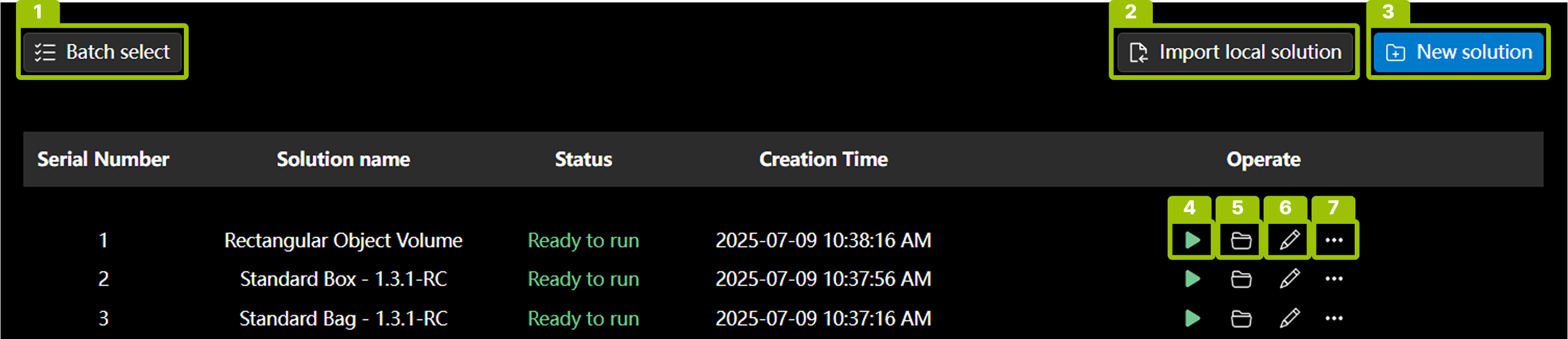
In this interface, you can view solutions and perform the following operations:
-
Batch operations (1): Perform batch export and delete operations on project solutions.
-
Import local solution (2): Import single or multiple existing project solutions (.epicpro files) from the local file system.
-
Create new solution (3): Create a new project solution.
-
Run solution (4): Run the project solution directly after configuration is complete.
-
Open solution configuration interface (5): Edit the configuration information of the current project solution.
-
Rename solution (6): Modify the name of the project solution.
-
More operations (7):
-
Copy: Copy the project solution and place it at the top of the list.
-
Export: Download the project solution to the local file system.
-
Delete: Remove the project solution from the solution list.
-
Solution Configuration Interface
Click Open in the solution or double-click the list row to open the solution configuration interface.
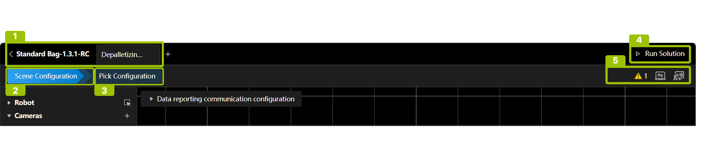
In this interface, you can perform workspace management (1) and complete specific solution configuration, including scene configuration (2), pick configuration (3), run solution (4), and view various statuses (5).
Workspace Management Interface (1)
-
Click + to create a new workspace.
-
Hover over the workspace name and click
 to rename, copy, delete, or edit the workspace ID.
| When copying a workspace, you can choose whether to synchronously copy the pick configuration. |
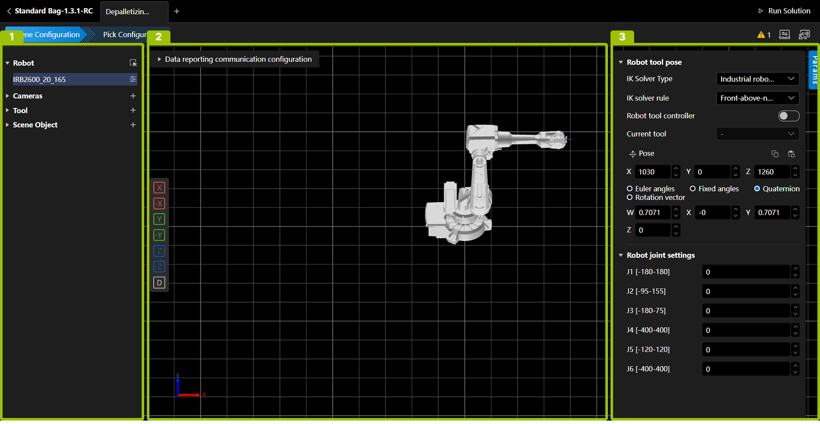
Scene Configuration Interface (2)
The scene configuration interface consists of the following three parts:
No. |
Area Name |
Description |
|---|---|---|
① |
Resource Tree |
Manage various resources used in the solution. |
② |
Scene Display Area |
Display models and poses of robots, tools, and scene objects. |
③ |
Parameter Settings Area |
Set detailed parameters for various resources. |
Scene display area view adjustment instructions:
Rotate view |
Press and hold the left mouse button and drag in any direction. |
Pan view |
Press and hold the right mouse button and drag in any direction. |
Zoom view |
Scroll the mouse wheel. |
For detailed scene configuration instructions, please refer to Scene configuration instructions.
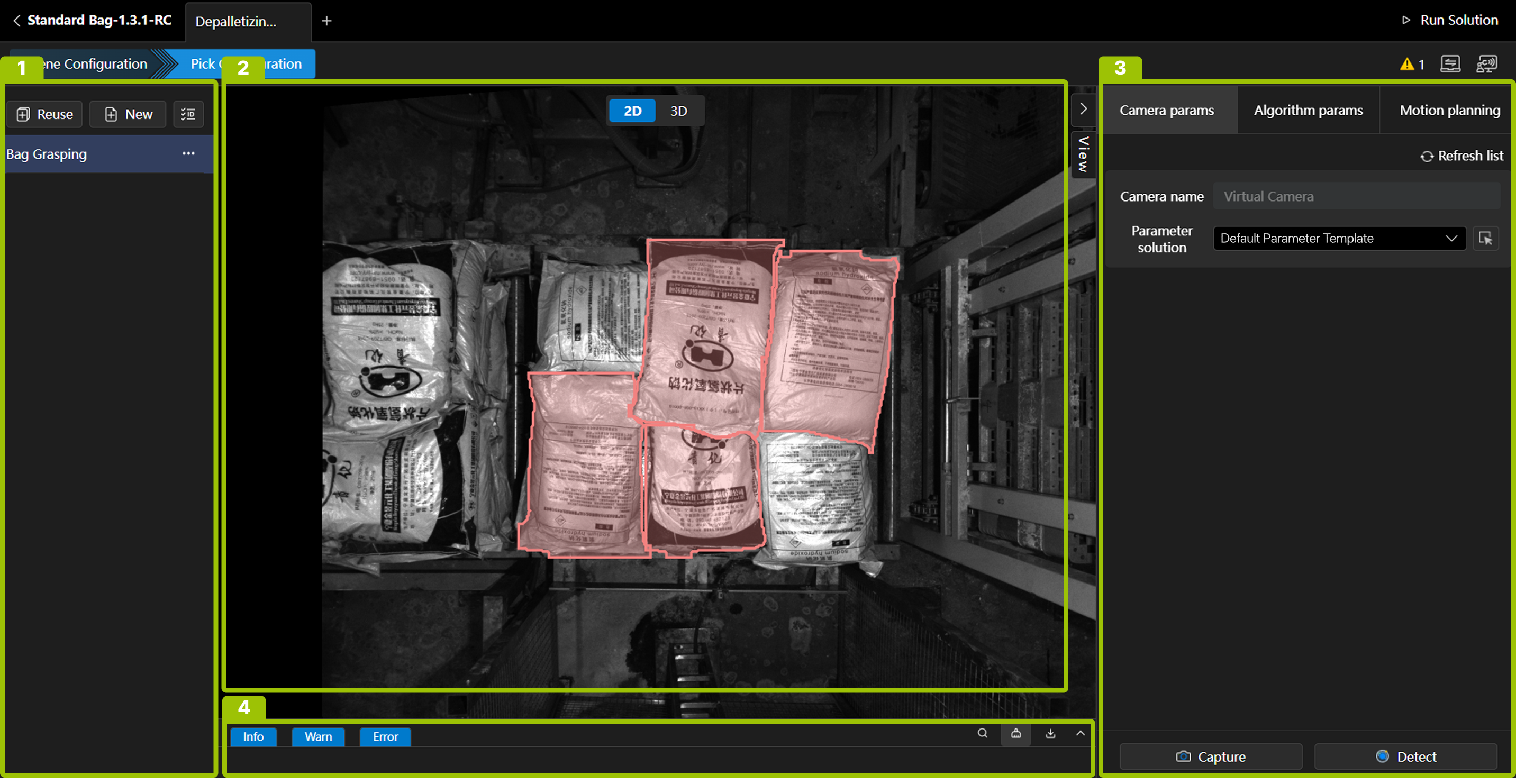
Pick Configuration Interface (3)
The pick configuration interface consists of the following four parts:
No. |
Area Name |
Description |
|---|---|---|
① |
Pick Configuration Management Area |
Create new, reuse, batch modify IDs, edit ID, rename, delete pick configurations. |
② |
View Display Area |
Display 2D view, 3D point cloud, robot, scene objects, etc. |
③ |
Parameter Settings Area |
Camera parameter display, algorithm parameter configuration, motion planning configuration. |
④ |
Log Display Area |
View, filter, search, download logs. |
For detailed pick configuration instructions, please refer to Grasping Configuration Guide.
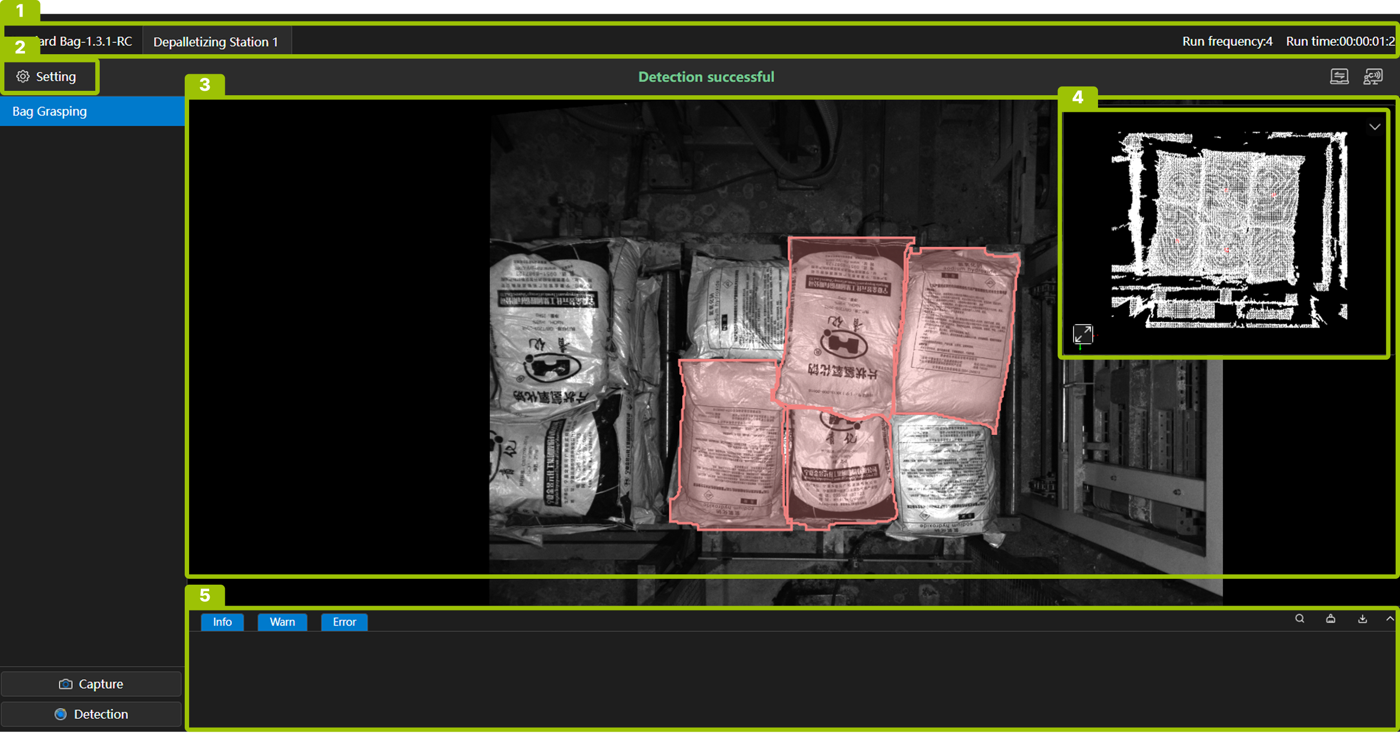
Solution Run Interface (4)
After completing the necessary scene configuration and pick configuration, click Run Solution in the upper right corner of the interface to enter the solution run interface.
This interface mainly consists of the following 4 parts:
No. |
Name |
Description |
|
|---|---|---|---|
① |
Information Bar |
This area displays the current solution and all workspaces, as well as the solution run count and run time. |
|
② |
Menu Bar |
Settings |
Manual Mode: When checked, you can manually trigger capture and detection in the software. |
Plugin Function: Use custom functions. |
|||
Runtime Screenshot: Save a screenshot of the run interface. |
|||
Sample Data Collection: Save .epicraw files. |
|||
HOOK Recompile: Compile custom scripts, script files need to be stored in /wwwroot/Extensions in the installation directory. |
|||
Exit Run: Exit the solution run interface. |
|||
Close Software: Close Epic Pro. |
|||
Shutdown IPC: Shutdown the industrial PC. |
|||
③ |
Scene Display Area |
This area displays robots, tool scene objects, point clouds, matching results, pick points, robot motion trajectories, etc. |
|
④ |
Camera View Display Area |
This area is used to display and switch between 2D images and point clouds. |
|
⑤ |
Log Display Area |
This area is used to view, filter, search, and download logs. |
|
Status Bar (5)
-
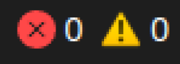 Click this icon to view error and warning information in the current solution.
 -
 This icon indicates the communication status of port 5700, which is used for interface command communication, such as triggering capture, detection, switching workspaces, switching pick configurations, etc.
 -
 This icon indicates the communication status of port 5800, which is used to receive real-time robot poses.