Three-Dimensional Orientation Representation Methods
Rotation Matrix
Rotation matrix is the most fundamental three-dimensional rotation representation method, describing rotational relationships between coordinate systems through 3×3 orthogonal matrices. Rotation matrices have strict mathematical properties: the matrix determinant is 1, and the matrix inverse equals its transpose. Although rotation matrices are mathematically rigorous, they have some problems in practical applications.
Rotation matrices require 9 parameters to describe 3 degrees of freedom rotation, creating redundancy. Additionally, rotation matrices are very unintuitive when describing rotations, making it difficult to directly understand their geometric meaning. Therefore, in practical engineering applications, other more intuitive or more compact representation methods are usually needed.
Euler Angles
Euler angles provide a relatively intuitive orientation representation method by decomposing complex three-dimensional rotations into 3 rotations around different axes. Due to multiple decomposition methods, Euler angles also have different definition methods, roughly divided into two categories: rotation around fixed axes (also called fixed angles) and rotation around axes after rotation.
RPY Euler Angle System
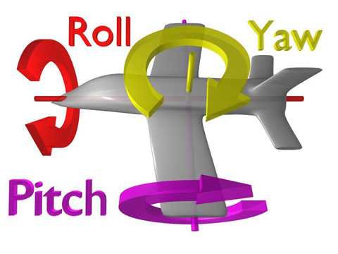
A commonly used Euler angle is RPY ("Yaw-Pitch-Roll"), equivalent to ZYX axis rotation:
-
Rotate around object’s Z-axis to get Yaw angle
-
Rotate around rotated Y-axis to get Pitch angle
-
Rotate around rotated X-axis to get Roll angle
This representation method is widely adopted in aerospace and robotics because it matches people’s intuitive understanding of object motion. Yaw angle controls object left-right turning, pitch angle controls up-down tilting, and roll angle controls lateral rotation.
Gimbal Lock Problem
Although Euler angles are relatively intuitive, they suffer from the gimbal lock problem. When pitch angle is positive or negative 90 degrees, the first rotation and third rotation will use the same axis, causing the system to lose one degree of freedom and creating singularities. Therefore, Euler angles are not suitable for interpolation and iteration.
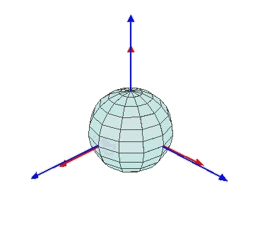
The gimbal lock occurrence process can be understood through the following image sequence:
Under normal conditions, yaw angle can independently control rotation around the Z-axis, with three rotation axes mutually independent.
When pitch angle is within normal range, the three rotation axes still maintain independence and can achieve complete three-dimensional rotation.
Roll angle under normal conditions controls rotation around the X-axis, independent of the other two axes.
However, when pitch angle reaches ±90 degrees, the first rotation axis (yaw axis) and third rotation axis (roll axis) become collinear or parallel, causing the system to lose one rotational degree of freedom and only achieve two degrees of freedom rotation. This phenomenon is called gimbal lock and is an inherent limitation of Euler angle representation.
|
Gimbal lock is not only a theoretical problem; in actual robot control, when robot end effectors approach singular orientations, sudden large rotations or motion discontinuities may occur, which is unacceptable in precision operations. |
Quaternions
Quaternions are a very effective three-dimensional rotation representation method that can overcome Euler angle singularity problems. They can be written as q = w + xi + yj + zk, where w, x, y, z are all real components. When used for rotations, quaternions must satisfy "unit norm," meaning w² + x² + y² + z² = 1.
Advantages:
-
Can avoid Euler angle "gimbal lock" problems, have no singularities, and are suitable for describing arbitrary three-dimensional orientations.
-
When composing multiple rotations, only quaternion multiplication is needed, which is efficient and numerically stable.
-
Suitable for rotation interpolation calculations. Spherical Linear Interpolation (SLERP) can generate smooth rotation paths between two quaternions, which is very useful in robot trajectory planning.
Disadvantages:
-
The relationship between quaternions and actual three-dimensional rotations is not easily understood through intuitive geometry, creating a high learning threshold.
-
When repeatedly using quaternions for transformations in computers, numerical errors can easily cause quaternions to no longer be unit quaternions, requiring periodic normalization.
-
Quaternions also have representation redundancy; q and -q represent the same rotation, which may cause confusion in some algorithms and requires special handling.
Rotation Vector
Rotation vector provides another concise three-dimensional rotation representation method based on the Rodrigues rotation formula. Any three-dimensional rotation can be understood as "rotating a certain number of degrees around a certain direction." For example, "rotate 30 degrees around x-axis," "rotate 45 degrees around [1,1,0] direction." This "direction" is represented by a three-dimensional vector (e.g., [1,0,0] represents x-axis direction), and "rotation angle" is represented by a number. Multiplying the two gives the rotation vector.
Advantages:
-
Rotation vector expression is concise and suitable for describing small-angle rotations.
-
Easy conversion to and from rotation matrices.
Disadvantages:
-
When rotation angles approach 180 degrees, rotation vector values become unstable; small changes may cause large changes in rotation results, requiring special attention in implementation.
-
Not as intuitive as Euler angles, nor as numerically robust as quaternions.
Rigid Body Transform
In robotics, merely describing orientation (rotation) is often insufficient; position (translation) must also be described simultaneously. Rigid body transform is proposed as a unified representation method to solve this problem.
Rigid body transform refers to rotation and movement (translation) of an object in three-dimensional space without changing the object’s shape and size. It is usually expressed using a 4×4 homogeneous matrix:
[ R T ]
[ 0 1 ]
Where R is a 3×3 rotation matrix and T is a 3×1 translation vector. This 4×4 matrix completely describes the position and orientation relationship of one coordinate system relative to another coordinate system.
The introduction of homogeneous coordinates allows rotation and translation to be uniformly represented using matrix multiplication. For a point P in space, its coordinates P' in the new coordinate system can be obtained through simple matrix multiplication: P' = T × P, where both P and P' are represented using homogeneous coordinates.
Advantages:
-
Can completely describe object position and orientation in space, suitable for unified representation of spatial motion.
-
Supports direct matrix multiplication for combining multiple transformations, suitable for robot kinematics, graphic transformations, etc.
-
Rigid body transformation matrices also have good numerical stability and do not accumulate excessive errors through continuous transformation operations.
|