Common Robot Data Formats
Cartesian Space Position Data Formats
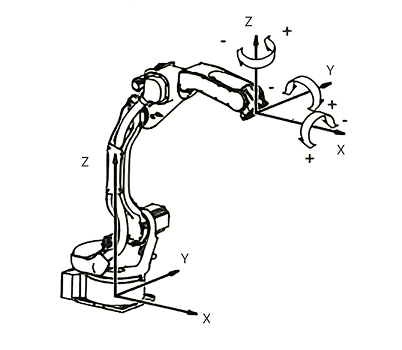
Cartesian space position data is the mathematical representation of robot end effector position and orientation in three-dimensional space. Different manufacturers adopt different orientation representation methods, but typically all include position coordinates (X, Y, Z) and orientation information.
|
Unless specifically noted otherwise, defaults are:
|
ABB
ABB robots use the format [X, Y, Z, q1, q2, q3, q4], where position uses millimeters as units and orientation is represented by unit quaternions. In quaternions, q1 is the real part, and q2, q3, q4 are imaginary parts in xyz directions respectively. Although ZYX Euler angles can be read on the teach pendant, the internal robtarget data structure actually uses unit quaternions to represent orientation.
ABB’s robtarget data type contains the following components:
Component Name |
Data Type |
Description |
trans |
pos |
Tool center point position expressed in mm (X, Y, Z) |
rot |
orient |
Tool orientation in unit quaternion form (q1, q2, q3, q4) |
robconf |
confdata |
Robot arm axis configuration (cf1, cf4, cf6, and cfx) |
extax |
extjoint |
External axis data for controlling external axis positions |
FANUC
FANUC robots use the format [X, Y, Z, W, P, R] to represent position and orientation data, where (X, Y, Z) are position coordinates and (W, P, R) are orientation angles. They use xyz fixed angles to represent orientation, also known as RPY angles.
Position and orientation data in the system are managed through user coordinate systems and tool coordinate systems. User coordinate systems allow users to define reference coordinate systems for work areas, while tool coordinate systems define tool end position and orientation.
YASKAWA
YASKAWA robots use [X, Y, Z, Rx, Ry, Rz] format, using xyz fixed angles to represent orientation.
KUKA
KUKA robots use [X, Y, Z, A, B, C] format, using zyx Euler angles to represent orientation. KUKA systems use POSITION, XYZWPR, XYZWPREXT, JOINTPOS, and PATH data types to represent position data.
KUKA’s POSITION data type contains the following components:
Component Type |
Quantity |
Unit |
Description |
REAL values (position) |
3 |
millimeters |
Representing X, Y, Z position coordinates |
REAL values (orientation) |
3 |
degrees |
Representing W, P, R orientation angles |
CONFIG data type |
1 |
Composed of 4 Boolean values and 3 integers, representing configuration of joint positions and turn numbers |
|
ROKAE
ROKAE robots use [X, Y, Z, q1, q2, q3, q4] format, using unit quaternions to represent orientation. Where q1 is the real part of unit quaternion, and q2, q3, q4 are imaginary parts in xyz directions respectively, similar to ABB format.
UR
UR robots use [X, Y, Z, Rx, Ry, Rz] format, using rotation vectors to represent orientation. In UR systems, [X, Y, Z] units are meters, and [Rx, Ry, Rz] units are radians.
Although xyz fixed angles can be read from the teach pendant, UR’s internal pose data uses rotation vectors to represent orientation. Therefore, the data format sent to robots should preferably be [X, Y, Z, Rx, Ry, Rz].
Other Brand Formats
EFORT and ESTUN robots both use [X, Y, Z, A, B, C] format, using zyx Euler angles to represent orientation.
ELITE robots use [X, Y, Z, Rx, Ry, Rz] format, using xyz fixed angles to represent orientation.
|
Common robot orientation representation methods include: 3x3 rotation matrices, fixed angles (XYZ fixed angles/RPY), Euler angles (ZYX Euler angles), unit quaternions, rotation vectors, and equivalent axis-angle. The difference between fixed angles and Euler angles lies in left multiplication (absolute transformation) versus right multiplication (relative transformation), therefore XYZ fixed angles (RPY) are equivalent to ZYX Euler angles. |
Speed Data Formats
Robot speed data defines the robot’s movement velocity, including joint space velocity and Cartesian space velocity. Different manufacturers adopt different strategies for speed data representation and control.
ABB
ABB uses the speeddata data type to define robot motion speed parameters. This data type contains four main components: v_tcp (tool center point speed in mm/s), v_ori (TCP reorientation speed in degrees/second), v_leax (linear external axis speed in mm/s), and v_reax (rotational external axis speed in degrees/second).
ABB’s speeddata data type contains the following components:
| Component Name | Data Type | Unit | Description |
|---|---|---|---|
v_tcp |
num |
mm/s |
Tool center point rate. If using stationary tool or coordinated external axes, specifies rate relative to workpiece |
v_ori |
num |
°/s |
TCP reorientation rate. If using stationary tool or coordination, specifies rate relative to workpiece |
v_leax |
num |
mm/s |
Linear external axis rate |
v_reax |
num |
°/s |
Rotational external axis rate |
The system predefines speed data for moving robot arms and external axes as follows:
| Name | TCP Speed | Orientation | Linear External | Rotational External |
|---|---|---|---|---|
v5 |
5 mm/s |
500°/s |
5000 mm/s |
1000°/s |
v10 |
10 mm/s |
500°/s |
5000 mm/s |
1000°/s |
v20 |
20 mm/s |
500°/s |
5000 mm/s |
1000°/s |
v30 |
30 mm/s |
500°/s |
5000 mm/s |
1000°/s |
v40 |
40 mm/s |
500°/s |
5000 mm/s |
1000°/s |
v50 |
50 mm/s |
500°/s |
5000 mm/s |
1000°/s |
v60 |
60 mm/s |
500°/s |
5000 mm/s |
1000°/s |
v80 |
80 mm/s |
500°/s |
5000 mm/s |
1000°/s |
v100 |
100 mm/s |
500°/s |
5000 mm/s |
1000°/s |
v150 |
150 mm/s |
500°/s |
5000 mm/s |
1000°/s |
v200 |
200 mm/s |
500°/s |
5000 mm/s |
1000°/s |
v300 |
300 mm/s |
500°/s |
5000 mm/s |
1000°/s |
v400 |
400 mm/s |
500°/s |
5000 mm/s |
1000°/s |
v500 |
500 mm/s |
500°/s |
5000 mm/s |
1000°/s |
v600 |
600 mm/s |
500°/s |
5000 mm/s |
1000°/s |
v800 |
800 mm/s |
500°/s |
5000 mm/s |
1000°/s |
v1000 |
1000 mm/s |
500°/s |
5000 mm/s |
1000°/s |
v1500 |
1500 mm/s |
500°/s |
5000 mm/s |
1000°/s |
v2000 |
2000 mm/s |
500°/s |
5000 mm/s |
1000°/s |
v2500 |
2500 mm/s |
500°/s |
5000 mm/s |
1000°/s |
v3000 |
3000 mm/s |
500°/s |
5000 mm/s |
1000°/s |
v4000 |
4000 mm/s |
500°/s |
5000 mm/s |
1000°/s |
v5000 |
5000 mm/s |
500°/s |
5000 mm/s |
1000°/s |
v6000 |
6000 mm/s |
500°/s |
5000 mm/s |
1000°/s |
v7000 |
7000 mm/s |
500°/s |
5000 mm/s |
1000°/s |
vmax |
Depends on robot model |
500°/s |
5000 mm/s |
1000°/s |
FANUC
Movement Speed Control:
FANUC supports multiple movement speed control methods. During movement, movement override can be specified for joint interpolation and linear interpolation motions in running programs. Movement override range is 1-100%. During movement, program speeds can also be reduced to set values.
Movement speeds can be represented in the following ways:
-
Percentage representation (%): Percentage relative to maximum speed, no position variables required, no auxiliary functions used.
-
Time representation (seconds): Can be specified with four decimal places in the range 0.1-3600 seconds. Movement time includes acceleration and deceleration time. During PTP movement, all joints move for the specified time simultaneously.
-
Speed representation (mm/sec): Can be specified with Cartesian coordinate system speed in the range 0.1-32000 mm/sec.
-
Feed rate representation (cm/min): Can be specified with feed rate in the range 0.1-12000 cm/min.
Motion Type Control:
FANUC provides flexible motion control methods, supporting joint interpolation motion and linear interpolation motion:
-
Joint interpolation motion (JP): For example, JP[1] 50% FINE means 50% speed precise positioning
-
Linear interpolation motion (LP): For example, LP[1] 100mm/sec FINE means linear motion at 100mm/s precise positioning
-
Circular interpolation motion (CP): Used for circular trajectory motion control
YASKAWA
YASKAWA robots support three main motion types: MOVJ (joint interpolation), MOVL (linear interpolation), MOVC (circular interpolation), each with dedicated parameters and speed units.
MOVJ |
Function |
Move to taught position using joint interpolation. |
|
Additional Items |
Position data, base axis position data, tool axis position data |
Not displayed on screen |
|
VJ= (playback speed) |
VJ: 0.01-100.00% |
||
PL= (positioning level) |
PL: 0-8 |
||
NWAIT |
|||
UNTIL statement |
|||
ACC= (acceleration adjustment ratio) |
ACC: 20-100% |
||
DEC= (deceleration adjustment ratio) |
DEC: 20-100% |
||
Usage Example |
MOVJ VJ=50.00 PL=2 NWAIT UNTIL IN#(16)=ON |
||
MOVL |
Function |
Move to taught position using linear interpolation. |
|
Additional Items |
Position data, base axis data, tool axis position data |
Not displayed on screen |
|
V= (playback speed), VR= (orientation playback speed), VE= (external axis playback speed), VMAX= (VMAX speed) |
V: 0.1-1500.0 mm/sec+1-9000 cm/min, VR: 0.1-360.0 deg/sec, VE: 0.01-100.00%, VMAX: 50-100% |
||
PL= (positioning level) |
PL: 0-8 |
||
CR= (corner radius) |
CR: 0.1-6563.5mm |
||
NWAIT |
|||
UNTIL statement |
|||
ACC= (acceleration adjustment ratio) |
ACC: 20-100% |
||
DEC= (deceleration adjustment ratio) |
DEC: 20-100% |
||
Usage Example |
MOVL V=138 PL=0 NWAIT UNTIL IN#(16)=ON |
||
MOVC |
Function |
Move to taught position using circular interpolation. |
|
Additional Items |
Position data, base axis data, tool axis position data |
Not displayed on screen. |
|
V= (playback speed), VR= (orientation angle playback speed), VE= (external axis playback speed) |
Same as MOVL. |
||
PL= (positioning level) |
PL: 0-8 |
||
NWAIT |
|||
ACC= (acceleration adjustment ratio) |
ACC: 20-100% |
||
DEC= (deceleration adjustment ratio) |
DEC: 20-100% |
||
COORD= (circular pose control specification) |
COORD: 0-1 |
||
FPT: circular endpoint specification |
|||
Usage Example |
MOVC V=138 PL=0 NWAIT |
||
|
Currently we have written speed data in D variables, causing robot operating speeds to not match the actual representation shown in the table below. |
KUKA
KUKA robots support three main motion types: PTP (point-to-point motion), LIN (linear motion), and CIRC (circular motion), each with corresponding speed parameter setting methods.
PTP:
PTP motion uses joint space motion, achieving precise positioning by controlling speed percentages of each axis.
| Parameter Type | Parameter Name | Value Range | Description |
|---|---|---|---|
Speed Control |
$VEL_AXIS[x] |
1-100% |
Controls speed percentage of each axis |
Acceleration Control |
$ACC_AXIS[x] |
System defined |
Acceleration control for each axis |
LIN/CIRC:
Trajectory motion uses Cartesian space motion with richer speed parameters, supporting independent control of linear and orientation speeds.
| Parameter Type | Parameter Name | Unit | Description |
|---|---|---|---|
Speed Control |
$VEL.CP |
m/s |
Trajectory speed, controls TCP linear motion speed in space |
$VEL.ORI1 |
°/s |
Rotation speed, controls orientation rotation speed around A and B axes |
|
$VEL.ORI2 |
°/s |
Turning speed, controls rotation speed around C axis (tool X-axis) |
|
Acceleration Control |
$ACC.CP |
m/s² |
Trajectory acceleration, controls acceleration/deceleration of linear motion |
$ACC.ORI1 |
°/s² |
Rotation acceleration, controls acceleration/deceleration of orientation changes |
|
$ACC.ORI2 |
°/s² |
Turning acceleration, controls acceleration/deceleration of rotation around tool axis |
ROKAE
ROKAE robot systems provide unified speed commands to control robot motion speed, defining motion speeds for robots and external axes.
The speed command contains the following core parameters:
Parameter Name |
Data Type |
Parameter Description |
Value Range |
per |
double |
Joint speed percentage, specifies motion speed during joint movement, applicable to MoveAbsJ and MoveJ commands |
1% ~ 100% |
tcp |
double |
TCP linear speed, defines tool center point linear speed |
0.001 mm/s ~ 7000 mm/s |
ori |
double |
Spatial rotation speed, defines tool rotation speed |
0.001°/s ~ 500°/s |
exj_l |
double |
External axis linear speed, defines motion speed of external linear axes |
0 mm/s ~ 2000 mm/s |
exj_r |
double |
External axis angular speed, defines motion speed of external rotational axes |
0°/s ~ 300°/s |
The system predefines common speed variables as follows:
| Name | Joint Speed Percentage | TCP Linear Speed | Spatial Rotation Speed | External Axis Angular Speed | External Axis Linear Speed |
|---|---|---|---|---|---|
v5 |
1% |
5 mm/s |
200°/s |
0°/s |
0 mm/s |
v10 |
3% |
10 mm/s |
200°/s |
0°/s |
0 mm/s |
v25 |
5% |
25 mm/s |
200°/s |
0°/s |
0 mm/s |
v30 |
5% |
30 mm/s |
200°/s |
0°/s |
0 mm/s |
v40 |
5% |
40 mm/s |
200°/s |
0°/s |
0 mm/s |
v50 |
5% |
50 mm/s |
200°/s |
0°/s |
0 mm/s |
v60 |
8% |
60 mm/s |
200°/s |
0°/s |
0 mm/s |
v80 |
8% |
80 mm/s |
200°/s |
0°/s |
0 mm/s |
v100 |
10% |
100 mm/s |
200°/s |
0°/s |
0 mm/s |
v150 |
15% |
150 mm/s |
200°/s |
0°/s |
0 mm/s |
v200 |
20% |
200 mm/s |
200°/s |
0°/s |
0 mm/s |
v300 |
30% |
300 mm/s |
200°/s |
0°/s |
0 mm/s |
v400 |
40% |
400 mm/s |
200°/s |
0°/s |
0 mm/s |
v500 |
50% |
500 mm/s |
200°/s |
0°/s |
0 mm/s |
v600 |
60% |
600 mm/s |
200°/s |
0°/s |
0 mm/s |
v800 |
70% |
800 mm/s |
200°/s |
0°/s |
0 mm/s |
v1000 |
100% |
1000 mm/s |
200°/s |
0°/s |
0 mm/s |
v1500 |
100% |
1500 mm/s |
200°/s |
0°/s |
0 mm/s |
v2000 |
100% |
2000 mm/s |
200°/s |
0°/s |
0 mm/s |
v3000 |
100% |
3000 mm/s |
200°/s |
0°/s |
0 mm/s |
v4000 |
100% |
4000 mm/s |
200°/s |
0°/s |
0 mm/s |
v5000 |
100% |
5000 mm/s |
200°/s |
0°/s |
0 mm/s |
v6000 |
100% |
6000 mm/s |
200°/s |
0°/s |
0 mm/s |
v7000 |
100% |
7000 mm/s |
200°/s |
0°/s |
0 mm/s |
UR
UR robots use different speed data formats in teach programming and script programming. In teach programming, speed data format uses degrees and millimeters as units, while in script programming, radians and meters are used.
UR systems support three movement types: moveJ (executes calculated movement in robot arm joint space), moveL (causes tool to move linearly between waypoints), and moveP (causes tool to move linearly through circular blend zones at constant speed).
Corner Zone Data
Corner zone data defines smooth transition methods between robot path points, which is crucial for achieving continuous and efficient robot motion. Different manufacturers adopt different corner processing strategies.
ABB
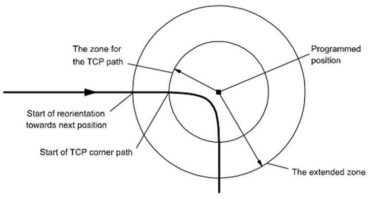
ABB robots use the zonedata data type to define corner zone parameters. This data type determines robot motion behavior at path points. Corner zone parameters can control whether the robot completely stops at target positions (precise positioning) or smoothly passes through target positions as fly-by points.
ABB’s zonedata data type contains the following components:
Component Name |
Data Type |
Description |
finep |
bool |
Specifies whether motion ends with stop point or fly-by point. TRUE means motion ends with stop point and program execution will not continue until robot reaches stop point. FALSE means motion ends with fly-by point and program execution continues. |
pzone_tcp |
num |
TCP zone radius (millimeters), defining zone as minimum relative size of zone |
pzone_ori |
num |
Tool reorientation zone radius (millimeters), defining radius as TCP distance from programmed point |
pzone_eax |
num |
External axis zone radius (millimeters), defining radius as TCP distance from programmed point |
zone_ori |
num |
Tool reorientation zone radius (degrees), meaning rotation angle about workpiece if robot is holding workpiece |
zone_leax |
num |
Linear external axis zone radius (millimeters) |
zone_reax |
num |
Rotational external axis zone radius (degrees) |
The system predefines common corner zone configurations as follows:
Path Zone |
Zone |
|||||
Name |
TCP Path |
Orientation |
External Axis |
Orientation |
Linear Axis |
Rotational Axis |
fine |
0 mm |
0 mm |
0 mm |
0° |
0 mm |
0° |
z0 |
0.3 mm |
0.3 mm |
0.3 mm |
0.03° |
0.3 mm |
0.03° |
z1 |
1 mm |
1 mm |
1 mm |
0.1° |
1 mm |
0.1° |
z5 |
5 mm |
8 mm |
8 mm |
0.8° |
8 mm |
0.8° |
z10 |
10 mm |
15 mm |
15 mm |
1.5° |
15 mm |
1.5° |
z15 |
15 mm |
23 mm |
23 mm |
2.3° |
23 mm |
2.3° |
z20 |
20 mm |
30 mm |
30 mm |
3.0° |
30 mm |
3.0° |
z30 |
30 mm |
45 mm |
45 mm |
4.5° |
45 mm |
4.5° |
z40 |
40 mm |
60 mm |
60 mm |
6.0° |
60 mm |
6.0° |
z50 |
50 mm |
75 mm |
75 mm |
7.5° |
75 mm |
7.5° |
z60 |
60 mm |
90 mm |
90 mm |
9.0° |
90 mm |
9.0° |
z80 |
80 mm |
120 mm |
120 mm |
12° |
120 mm |
12° |
z100 |
100 mm |
150 mm |
150 mm |
15° |
150 mm |
15° |
z150 |
150 mm |
225 mm |
225 mm |
23° |
225 mm |
23° |
z200 |
200 mm |
300 mm |
300 mm |
30° |
300 mm |
30° |
Corner zone data structure is as follows:
< data object of zonedata >
< finep of bool >
< pzone_tcp of num >
< pzone_ori of num >
< pzone_eax of num >
< zone_ori of num >
< zone_leax of num >
< zone_reax of num >
FANUC
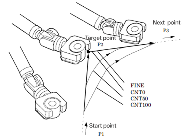
FANUC systems provide two main positioning types: FINE (precise positioning) and CNT (continuous positioning). FINE positioning type requires robots to completely stop at target positions before moving to next target positions. CNT positioning type allows robots to approach target positions without stopping at those positions while continuing motion to next positions.
YASKAWA
YASKAWA uses positioning level PL and corner radius CR to control corner zones. The system provides FINE positioning type (robot completely stops at target position before moving toward next target position) and CNT positioning type (robot approaches target position but does not stop at that position while continuing motion to next position).
KUKA
KUKA robots use multiple trajectory approximation parameters to control corner behavior, with different motion types adopting different approximation strategies. The system supports PTP (point-to-point), LIN (linear), and CIRC (circular) motion methods, each with corresponding trajectory approximation configurations.
Motion types and trajectory approximation parameters:
| Motion Type | Applicable Parameter | Description |
|---|---|---|
PTP |
C_PTP |
Trajectory approximation used only for PTP motion, causing target points to be trajectory approximated. Only C_PTP parameter is needed in PTP-PTP trajectory approximation |
PTP-CP |
C_DIS, C_ORI, C_VEL |
Trajectory approximation from PTP to Cartesian path, multiple parameters can be used in combination |
LIN/CIRC |
C_DIS, C_ORI, C_VEL |
Trajectory approximation for Cartesian path motion, supporting distance, orientation, and velocity parameters |
Detailed trajectory approximation parameters:
| Parameter Name | Applicable Motion | Unit | Parameter Description |
|---|---|---|---|
C_PTP |
PTP |
% |
Defines trajectory approximation percentage for PTP motion, controlling degree of target point approximation |
C_DIS |
LIN/CIRC/PTP-CP |
mm |
Distance parameter, trajectory approximation starts earliest when distance to target point is below $APO.CDIS value |
C_ORI |
LIN/CIRC |
° |
Orientation parameter, trajectory approximation starts earliest when dominant orientation angle is below $APO.CORI value |
C_VEL |
LIN/CIRC |
% |
Velocity parameter, trajectory approximation starts earliest when velocity toward target point drops below $APO.CVEL value during deceleration phase |
Motion combinations and parameter usage:
-
PTP single motion: Only uses C_PTP parameter, setting approximation percentage through $APO.CPTP
-
PTP-CP combination motion: Can use C_DIS, C_ORI, C_VEL parameters for smooth transition from point-to-point motion to Cartesian path
-
LIN/CIRC motion: Supports combination use of C_DIS, C_ORI, C_VEL three parameters for precise trajectory control
|
In practical applications:
|
ROKAE
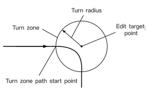
ROKAE robots provide multiple methods for setting smooth transition distances. Zone variables define motion intervals or transition zone sizes between two motion trajectories. During stop processing, robots move to target points with zero velocity at target points before continuing to next commands. During transition processing, robots do not move to target points but start turning toward next target points when several distance millimeters away from target points.
ROKAE systems predefine common turn zone variables, with direct correspondence between Cartesian space turn zone sizes and turn percentages:
Name |
Cartesian Space Turn Zone Size |
Turn Percentage |
fine |
0 mm |
0% |
z1 |
1 mm |
1% |
z5 |
5 mm |
3% |
z10 |
10 mm |
5% |
z15 |
15 mm |
8% |
z20 |
20 mm |
10% |
z30 |
30 mm |
15% |
z40 |
40 mm |
20% |
z50 |
50 mm |
25% |
z60 |
60 mm |
30% |
z80 |
80 mm |
40% |
z100 |
100 mm |
50% |
z150 |
150 mm |
75% |
z200 |
200 mm |
100% |
UR
UR robots support Blend Region functionality in path planning by setting corner radius parameter r (unit: m) to achieve smooth trajectory transitions. When corner radius is set for path points, robots will not completely stop at those points but smoothly transition to next path segments with circular trajectories.
After setting corner radius, robot trajectories form circular transitions near path points, avoiding sudden stop-start phenomena. Circle radius size directly affects trajectory smoothness and deviation distance from original paths. Smaller corner radii stay closer to original path points but motion is less smooth; larger corner radii provide smoother motion but deviate more from intended trajectories.
When adjacent path point corner zones overlap, situations become complex. If current path point corner zones overlap with previous or next path point corner radii, the system skips intermediate path points and connects directly to next valid points.
|
Corner zone parameter settings are directly related to distances between two motion points, requiring reasonable settings to ensure robot motion smoothness and efficiency. |
Robot Arm Configuration Data
Robot arm configuration data is crucial for correct robot motion control, defining current states and motion constraints of robot joints. This data often causes vision point inaccessibility issues due to improper settings.
ABB
ABB uses the confdata data type to define robot axis configuration. Using Cartesian coordinate systems, all robot arm positions can be defined and stored. When calculating robot arm solutions, usually two or more solutions may exist. These situations represent different possible positions or configurations for the robot arm. To clearly indicate one possible configuration, robot configuration is defined using four axis values.
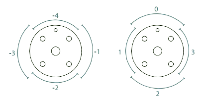
For rotational axes, the value defines the current quadrant of robot axis. Quadrants are numbered 0, 1, 2, etc., including negative numbers, with quadrant numbers related to current axis relationships. For 6-axis robots, quadrant 0 is the first quarter circle from zero position to 180°, i.e., 0° to 90°; quadrant 1 is the second quarter circle, i.e., 90° to 180°, and so on.
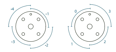
For 7-axis robots, quadrant 0 is a quarter circle centered on zero position, i.e., -45° to 45°; quadrant 1 is the second quarter circle in positive rotation, i.e., 45° to 135°, and so on.
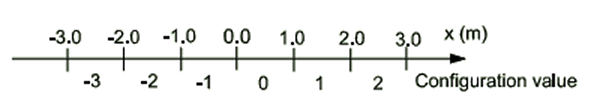
For linear axes, the value indicates the interval meter count for robot axes. For each axis, value 0 means a position between 0 to 1 meter, value 1 means a position between 1 to 2 meters. For negative values, -1 means a position between -1 to 0 meters, and so on.
Configuration Supervision:
For some robot types, if ConfL\On is set, configuration data (confdata) is also used to supervise programmed points related to linear movement. Configuration monitoring is not performed using ConfL\On, such as during Confl-joint movement configuration control.
Before starting specified motion, verification is performed to check if programmed configuration can be achieved. If impossible, the program stops. Upon motion completion (in zone or fine point), verification ensures robot has reached programmed configuration. Configuration supervision with ConfL\On varies among different robots.
| Robot Arm Type | Configuration Supervision Content |
|---|---|
6-axis robot arm |
Checks if axes 1, 4, and 6 do not move more than 180 degrees, and ordered movement does not require cfx changes (cfx only applies to serial link robots, not parallel link robots) |
4-axis robot arm |
Checks if axes 1 and 6 do not move more than 180 degrees |
Parallel arm robots (Delta robots) |
Checks if axis 4 does not move more than 180 degrees |
SCARA robots |
Checks if axes 1 and 4 do not move beyond 180 degrees, also verifies axis 2 flag |
7-axis robot arm |
Checks if axes 1, 4, and 6 do not move more than 180 degrees, and arranged movement does not require cfx changes |
Paint robot arm |
No configuration supervision implemented |
Robot Arm Configuration Data:
-
6-axis robot arm with serial lines
Three transition points exist in robot working range: cf1 for axis 1 quadrant number, cf4 for axis 4 quadrant number, and cf6 for axis 6 quadrant number.
cfx selects from eight possible robot configurations numbered 0 to 7. The table describes various configurations relative to three transition points
cfx
Relative to axis 1 brain center
Relative to lower arm brain center
Axis 5 angle
0
In front
In front
Positive
1
In front
In front
Negative
2
In front
Behind
Positive
3
In front
Behind
Negative
4
Behind
In front
Positive
5
Behind
In front
Negative
6
Behind
Behind
Positive
7
Behind
Behind
Negative
-
6-axis robot arm with parallel rods: Only uses configuration parameters cf1, cf4, and cf6.
-
4-axis robot arm: Only uses configuration parameter cf6.
-
Parallel arm robot arm: Only uses configuration parameter cf4.
-
SCARA robots: Only uses three configuration parameters cf1, cf4, and cfx. cfx value shows axis 2 angle flag. If axis 2 angle is negative, cfx is 1, otherwise cfx is 0.
-
7-axis robots: Uses four configuration parameters, cf1, cf4, and cf6 for joints 1, 4, and 6 respectively, cfx selects from 8 possible robot configurations. Method similar to other robots.
cfx
Axis 2 angle
Relative to lower arm wrist center
Axis 5 angle
0
Positive
In front
Positive
1
Positive
In front
Negative
2
Positive
Behind
Positive
3
Positive
Behind
Negative
4
Negative
In front
Positive
5
Negative
In front
Negative
6
Negative
Behind
Positive
7
Negative
Behind
Negative
-
Paint robot arm: Uses all four configuration parameters. cf1, cf4, cf6 for interfaces 1, 4, and 6 respectively, cfx for interface 5.
-
IRB 5500: Uses all four configuration parameters. cf1, cf4, cf6 for interfaces 1, 4, and 6 respectively, cfx parameter contains interface 5 quadrant number and four possible configurations for axes 2 and 3.
-
IRB 5350: Robot arm has two rotational axes (arm 1 and arm 2) and one linear axis (arm 3). cf1 for rotational axis 1, cfx for rotational axis 2, cf4 and cf6 not used.
Components:
| Component | Data Type | Rotational Axis | Linear Axis |
|---|---|---|---|
cf1 |
num |
Current quadrant of axis 1, expressed as positive or negative integer |
Current interval meters of axis 1, expressed as positive or negative integer |
cf4 |
num |
Current quadrant of axis 4, expressed as positive or negative integer |
Current interval meters of axis 4, expressed as positive or negative integer |
cf6 |
num |
Current quadrant of axis 6, expressed as positive or negative integer |
Current interval meters of axis 6, expressed as positive or negative integer |
cfx |
num |
For serial line robot arms and 7-axis robots, robot arm configuration expressed as integer in range 0 to 7. + For SCARA robots, robot arm configuration expressed as integer in range 0 to 1. + For paint robot arms, current quadrant of axis 5 expressed as positive or negative integer. + For other robot arms, current quadrant of axis 2 expressed as positive or negative integer. |
Current interval meters of axis 2, expressed as positive or negative integer |
FANUC
FANUC robots use configurations to specify position states of robot joints. Configuration refers to robot main body posture. For given Cartesian coordinate values (X, Y, Z, W, P, R), usually multiple configuration solutions exist. To determine unique robot positions, joint configuration and turn numbers for each axis must be clearly specified.
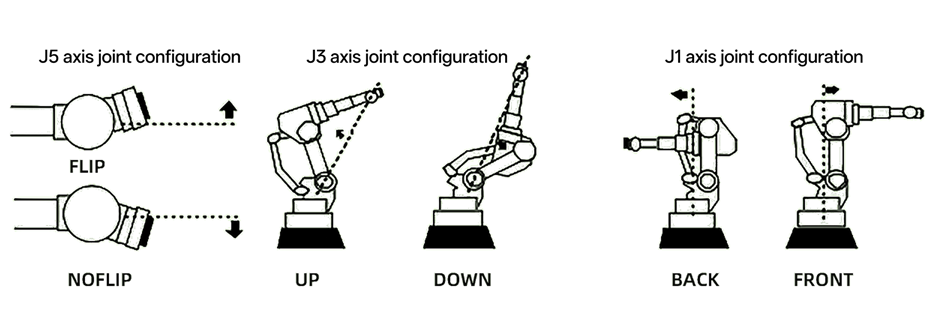
FANUC systems classify robot joint configurations into the following basic types:
Main Configuration States:
Configuration Item |
State Value |
Description |
FLIP/NOFLIP |
LEFT/RIGHT |
Indicates robot wrist (J5 axis) flip state, determining tool orientation |
UP/DOWN |
FRONT/BACK |
Represents robot arm (J3 axis) up/down configuration, affecting robot workspace utilization |
Elbow joint state |
UPPER/LOWER |
Describes robot elbow (J2 and J3 axis combination) configuration state |
Turn Number Range Definition:
FANUC systems use turn numbers to handle rotational axes exceeding ±180°:
Turn Number Value |
Angle Range |
Description |
1 |
180°~539° |
Positive angle range exceeding one rotation |
0 |
-179°~179° |
Standard angle range, no turns |
-1 |
-539°~-180° |
Negative angle range exceeding one rotation |
FANUC systems use dedicated system variables to manage and track rotational axis states:
Rotational Axis State Variables:
System Variable |
Function |
Application Description |
$SSCR_GRP[group].$TURN_AXIS[1] |
Manages first axis (base rotation axis) turn state |
Records J1 axis turn information for distinguishing multi-turn rotation positions |
$SSCR_GRP[group].$TURN_AXIS[2] |
Manages second axis (shoulder axis) turn state |
Records J2 axis turn information, affecting arm configuration |
$SSCR_GRP[group].$TURN_AXIS[3] |
Manages third axis (elbow axis) turn state |
Records J3 axis turn information, determining elbow up/down configuration |
Configuration Data Structure:
Data Component |
Data Type |
Description |
Joint Position |
JOINTPOS |
All joint angle values in degrees |
Configuration Flag |
CONFIG |
Describes robot current configuration state (FLIP, UP, etc.) |
Turn Information |
TURN |
Turn numbers for each axis, handling multi-turn rotations |
Validity Flag |
STATUS |
Indicates if this configuration is valid and reachable |
YASKAWA
YASKAWA robots use [fig_ctrl] to point to configuration information pointer (output). Syntax:
typedef unsigned int BITSTRING;Bit |
Description |
D00 |
0:Front 1:Back |
D01 |
0:Upper arm 1:Lower arm |
D02 |
0:Flip 1:No flip |
D03 |
0:R<180 1:R>=180 |
D04 |
0:T<180 1:T>=180 |
D05 |
0:S<180 1:S>=180 |
D06-D31 |
Reserved by manufacturer |
KUKA
KUKA robots use POSITION, XYZWPR, XYZWPREXT, JOINTPOS, and PATH data types to represent position data. POSITION data type contains three REAL values representing X, Y, Z position values in millimeters, three REAL values representing W, P, R orientations in degrees, and one CONFIG data type consisting of 4 Boolean values and 3 integers representing joint position and turn number configuration.
KUKA robot configuration data is defined through STATUS and TURN components. TCP position (X, Y, Z) and orientation (A, B, C) values are insufficient to clearly specify robot position. Because when TCP is identical, multiple axis positions may still exist. Status and turn directions determine unique positions from multiple possible axis positions.
STATUS
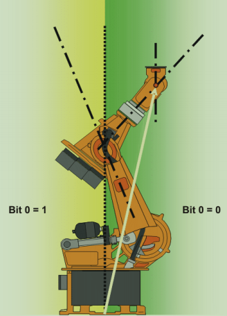
Bit 0: Overhead Area Detection
When axis 1 is at 0°, A1 coordinate system coincides with $ROBROOT coordinate system. When value is not 0°, A1 coordinate system moves with axis 1.
Position |
Value |
Overhead area |
Bit 0=1 |
Basic area |
Bit 0=0 |
When axis 1 is at 0°, A1 coordinate system coincides with $ROBROOT coordinate system. When value is not 0°, A1 coordinate system moves with axis 1.
Bit 1: Axis 3 Position
Corresponding angle when bit 1 value changes depends on robot type. For robots with related axes 3 and 4:
Position |
Value |
A3≥0° |
Bit 1=1 |
A3<0° |
Bit 1=0 |
For robots with offset axes 3 and 4, corresponding angle when bit 1 changes depends on offset magnitude.

Bit 2: Axis 5 Position
Position |
Value |
A5>0 |
Bit 2=1 |
A5≤0 |
Bit 2=0 |
Bit 3: Unused, always 0.
Bit 4: Drive Type Identification
Indicates whether points were taught using absolutely accurate robots.
Description |
Value |
Point not taught using absolutely accurate robot |
Bit 4=0 |
Point taught using absolutely accurate robot |
Bit 4=1 |
TURN
TURN parameters use 6 bits corresponding to 6 axes (A1-A6) turn states, with each bit recording whether corresponding axis is in negative angle range. This accurately distinguishes actual positions of robot axes during multi-turn rotations. Each bit determines axis value sign as follows:
-
Bit=0: Angle≥0°
-
Bit=1: Angle<0°
Value |
Bit 5 |
Bit 4 |
Bit 3 |
Bit 2 |
Bit 1 |
Bit 0 |
0 |
A6≥0° |
A5≥0° |
A4≥0° |
A3≥0° |
A2≥0° |
A1≥0° |
1 |
A6<0° |
A5<0° |
A4<0° |
A3<0° |
A2<0° |
A1<0° |