Terms and Concepts
Before using the software, please understand the following concepts for better comprehension and usage.
-
Project Solution
A project solution, or simply solution, is a comprehensive solution for 3D vision guidance projects that can handle one or more pick scenarios. A "Project Solution" consists of one or more "Workspaces".
-
Workspace
A workspace, or simply space, is the specific configuration and pick settings for a particular pick scenario, including scene configurations such as robots and cameras, as well as pick configurations such as vision algorithms and motion planning.
-
ROI
ROI (Region of Interest) is a specific region in the data. Setting an ROI can improve processing efficiency and accuracy, save resources, etc.
-
Hand-Eye Calibration
Hand-eye calibration refers to calculating the transformation relationship between the robot coordinate system and the camera coordinate system by collecting the poses of calibration objects captured by the camera and robot poses. Using the calculated transformation matrix, target points in the camera coordinate system can be transformed to the robot coordinate system, enabling robot operations under 3D vision guidance. The accuracy of hand-eye calibration is crucial and directly affects system accuracy and stability.
-
Tool
End tools are devices specifically designed and installed at the mechanical interface to enable the robot to complete its tasks, such as grippers and suction cups.
-
Scene Object
Scene objects refer to various objects in the actual robot working scene, generally including pallets, bins, racks, etc.
-
Motion Planning
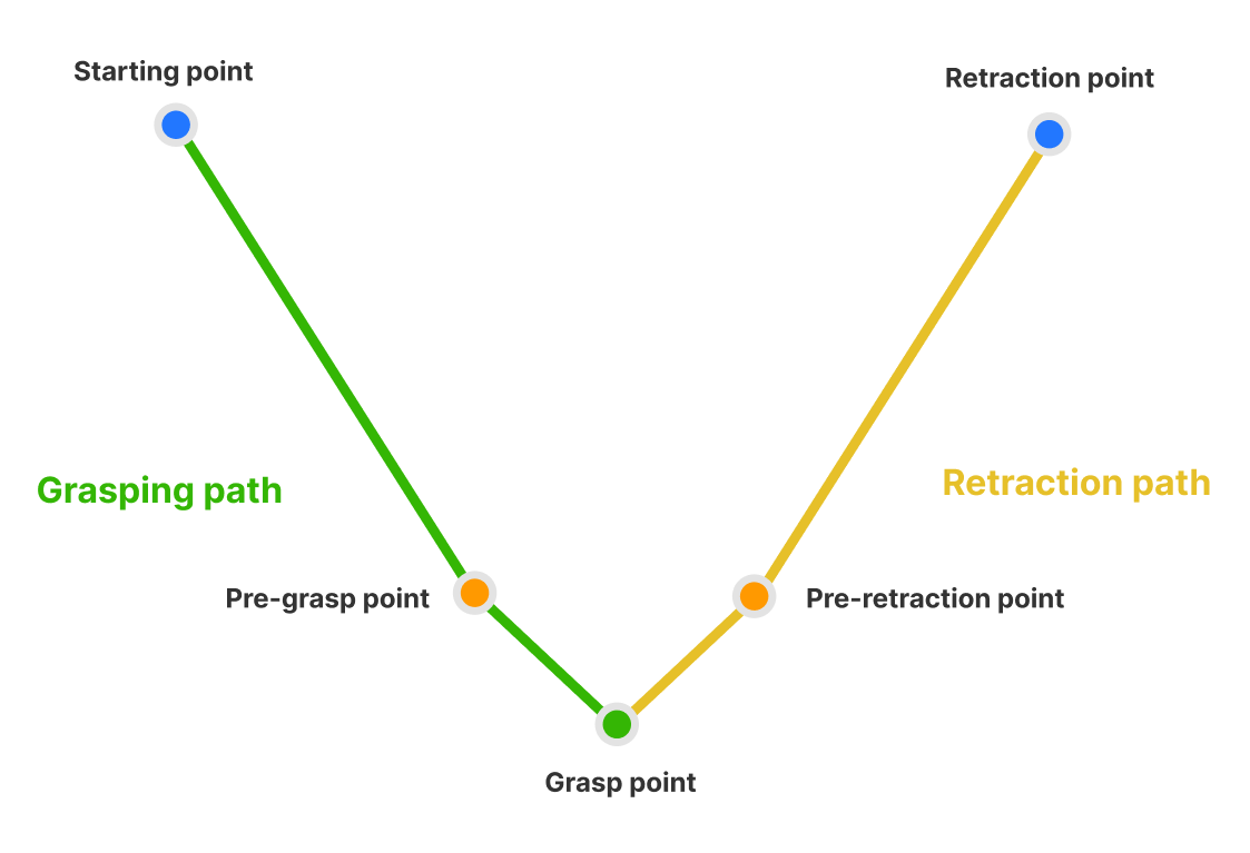
The motion planning module calculates the optimal path sequence from the robot’s starting position to the target pick position. This module uses a new algorithm architecture that supports setting multiple pre-pick points and pre-retreat points, enabling the robot to intelligently select the most suitable approach method and safe retreat route, effectively handling obstacles in complex working environments. The module’s planning details panel intuitively displays detection results for each path, combined with precise trajectory display and collision area visualization, greatly simplifying path configuration and debugging, allowing engineers to complete robot application solution construction and optimization more quickly.
-
Collision Grid Edge Length
During collision detection, the point cloud itself does not directly participate in collision detection. Instead, the 3D space where the point cloud is distributed is recursively divided into eight sub-cubes until the cube edge length reaches the set collision grid length. If these cubes collide with other objects, the point cloud is considered to have collided. By adjusting the collision grid edge length, the accuracy and efficiency of collision detection are affected.
In collision detection, the collision grid edge length directly affects detection accuracy: the smaller the collision grid edge length, the more accurate the collision detection, but the longer the calculation time.