Reference Coordinate Systems
Basic Coordinate System Details
Base Coordinate System
The base coordinate system is the fundamental coordinate system of industrial robots, representing the robot’s absolute position in space. If the industrial robot is installed on the ground, this coordinate system is mostly located on the base, with the origin at the center of the robot base. The XY plane coincides with the base plane, typically with the X-axis direction pointing toward the robot’s "back" direction, and the Z-axis direction pointing vertically upward. If the robot is mounted inverted, the Z-axis points downward.
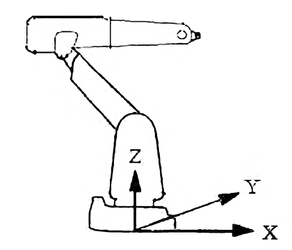
Coordinate Definition:
-
Origin: Located at the center of robot base
-
XY plane: Coincides with base plane
-
X-axis direction: Usually points toward robot "back" direction
-
Z-axis direction: Vertically upward (normal installation) or downward (inverted installation)
The base coordinate system serves as the absolute reference frame for the robot workspace, with all positions and orientations defined relative to the base coordinate system. In simple applications, users can directly program robot actions in the base coordinate system.
World Coordinate System
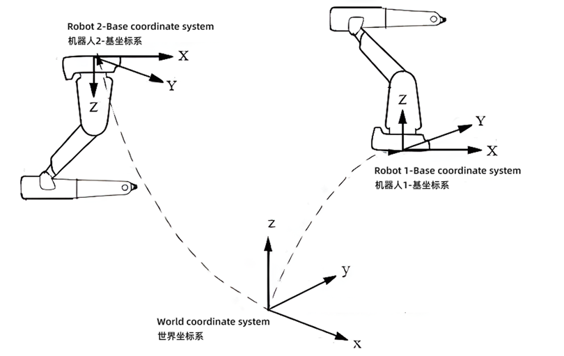
Generally, the world coordinate system and base coordinate system coincide. If the robot is installed on the ground, programming based on the base coordinate system is very simple. However, in certain special cases, using a world coordinate system can bring greater convenience.
Application Scenarios:
-
Non-standard installation: When robots are mounted inverted or at an angle, programming with the base coordinate system is difficult because axis directions differ from main directions in the workspace. Defining a world coordinate system can simplify programming work.
-
Multi-robot collaboration: When multiple robots work in the same workspace within a factory, using a unified world coordinate system enables robots to communicate and coordinate with each other, avoiding collisions and interference.
User Coordinate System
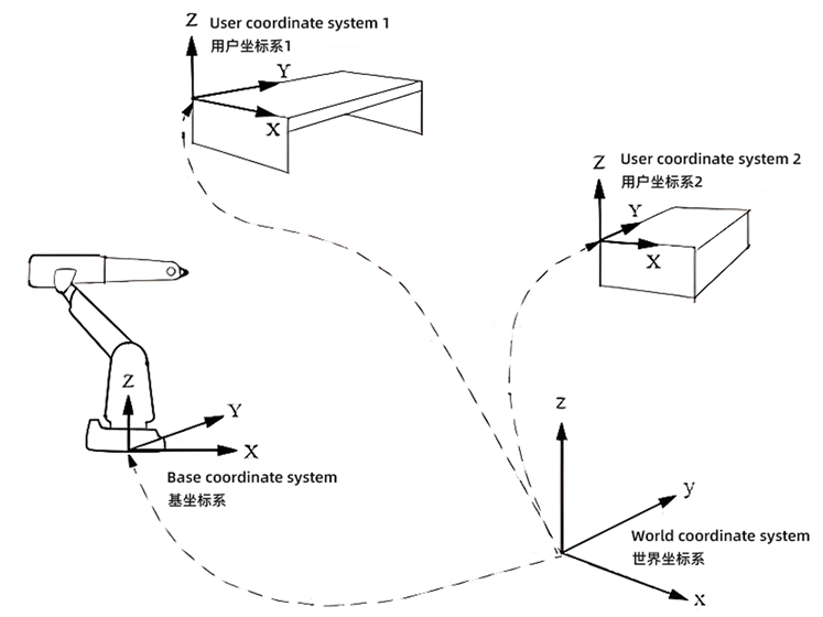
User coordinate systems are defined based on the world coordinate system. Industrial robot applications typically involve workbenches or fixtures. User coordinate systems are designed to handle different fixtures or workbenches with different positions and orientations, typically defining an independent user coordinate system for each fixture or workbench.
By establishing user coordinate systems, when workpiece or workbench positions change, robot programs can quickly adapt by adjusting user coordinate system parameters without rewriting entire programs, greatly improving programming flexibility and efficiency.
End Effector Related Coordinate Systems
Flange Coordinate System
The flange coordinate system is a coordinate system fixed at robot factory delivery and cannot be changed. The origin is located at the center of the six-axis robot flange, the XY plane coincides with the flange plane, and the Z-axis direction extends perpendicularly outward from the flange.
The flange coordinate system serves as the reference frame for robot end effectors, with all tool coordinate systems defined based on the flange coordinate system. This coordinate system provides a unified reference standard for various tools mounted on the flange.
Coordinate Definition:
-
Origin: Located at the center of six-axis robot flange
-
XY plane: Coincides with flange plane
-
Z-axis direction: Extends perpendicularly outward from flange
Tool Coordinate System and TCP
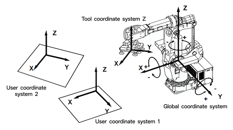
The tool coordinate system is a coordinate system established with the Tool Center Point (TCP) as origin, describing the positional relationship of robot end tools relative to the flange coordinate system. The Tool Center Point is the origin of the tool coordinate system and is one of the key technologies in industrial robotics.
Tool coordinate system parameters can be obtained through robot teaching or by precisely measuring tool dimensions. TCP setup facilitates programming and program adjustment: when the robot moves, the position, path, precision, and speed commonly referred to for the robot actually refer to the TCP’s position, path, precision, and speed.
The tool coordinate system enables robots to precisely control tool endpoint positions rather than flange center, which is crucial for precision operations such as welding, assembly, and grasping.
Vision System Coordinate Systems
Camera Coordinate System
The camera coordinate system is fundamental to robot vision systems, established with the camera optical center as origin. Its function is to convert image information captured by cameras into three-dimensional spatial coordinate information, providing basic data for robot vision positioning and recognition.
Coordinate Definition:
-
Origin: Calibration center position of camera lens and sensor
-
Z-axis direction: Camera downward (shooting direction)
-
X-axis direction: Camera long edge direction, usually negative X-axis direction
-
Y-axis direction: Follows right-hand rule
Calibration Board Coordinate System
The calibration board coordinate system is the standard reference coordinate system during hand-eye calibration processes. The calibration board coordinate system provides standard geometric references for establishing transformation relationships between camera coordinate systems and robot coordinate systems, serving as an important foundation for achieving precise hand-eye calibration.
Coordinate Definition:
-
Origin: Right-angle vertex at diagonal corner of calibration board label
-
X-axis: Along calibration board short edge direction
-
Y-axis: Along calibration board long edge direction
-
Z-axis: Perpendicular to calibration board surface
Model Coordinate System
The model coordinate system is the coordinate system for three-dimensional model data, typically related to point cloud data. Initially consistent with camera coordinate system, after alignment the origin moves to point cloud center, with coordinate axes defined referencing model bounding box directions.
In three-dimensional vision recognition and positioning, the model coordinate system provides coordinate correspondence between models and actual workpieces, enabling robots to accurately position and operate workpieces based on vision recognition results.
Special Application Coordinate Systems
Container Coordinate System
The container coordinate system is a coordinate system established with containers or workbenches as reference, facilitating batch processing of workpieces. The origin is typically selected at a corner of the container, with coordinate axes established along container edge directions, aimed at simplifying position calculations for batch workpieces.
In automated production, container coordinate systems facilitate orderly operations on multiple workpieces in containers. Through regular coordinate offsets, each workpiece position in containers can be accessed sequentially without individually teaching each workpiece position.
Workpiece Coordinate System
The workpiece coordinate system describes the positional relationship of workpieces relative to the base coordinate system, using the base coordinate system as reference point to describe workpiece (or workbench) positional relationships relative to robot base. When workpiece positions change, quick adaptation is achieved by adjusting workpiece coordinate system parameters.
The main function of workpiece coordinate systems is to achieve robot program flexibility. When workpiece positions change, only workpiece coordinate system parameters need adjustment without modifying entire program point data, greatly improving production efficiency and program reusability.
Coordinate System Transformation Relationships
In robot vision systems, based on different camera installation positions, there are two main hand-eye calibration methods corresponding to different coordinate system transformation relationships.
Eye-to-hand calibration refers to cameras fixed outside the robot workspace, establishing fixed relationships between cameras and robot base. In this configuration, the transformation relationship is between camera coordinate system and robot base coordinate system, with the transformation matrix describing camera position and orientation relative to robot base.
Eye-in-hand calibration refers to cameras mounted on robot end effectors, moving with robot motion. In this configuration, the transformation relationship is between camera coordinate system and robot flange coordinate system, with the transformation matrix describing fixed camera position and orientation relative to robot flange.
Three Essential Elements of Robot Motion Control
When robots execute motion commands, three key elements must be specified: point data (coordinate values of target position), tool coordinate system TCP (which tool’s coordinate system to use), and reference coordinate system (which coordinate system the point data is defined relative to).
Different robot brands have different representations for these elements. KUKA robots use $BASE to define reference coordinate system and $TOOL to define tool coordinate system. ABB robots use wobj (workpiece object) to define reference coordinate system and tool (tool object) to define tool coordinate system.
Practical Application Case: Palletizing Operations
Palletizing operations are typical applications of industrial robots. Flexible programming strategies can be achieved through different coordinate system combinations.
-
Strategy 1: Adjust workpiece coordinate system
Fix tool and point positions, adjust workpiece coordinate system. In this method, tool coordinate system (tool) remains unchanged, point data (P) remains unchanged, and workpiece coordinate system (wobj) is adjusted according to palletizing layers. The advantage of this method is simple program structure, requiring only one parameter adjustment to achieve different layer palletizing.
-
Strategy 2: Adjust point data
The second method fixes tool and workpiece coordinate systems, adjusting point data. Tool coordinate system (tool) remains unchanged, workpiece coordinate system (wobj) remains unchanged, and point data (P) is calculated and adjusted according to palletizing requirements. This method requires calculation for each layer’s points but can achieve more flexible palletizing patterns.