Common Robot Classifications
Classification by Structural Form
Articulated Robots
Articulated robots are connected through multiple rotary joints, simulating the movement patterns of human arms. According to different joint numbers and configurations, they are mainly divided into the following types:
3-Axis Articulated Robots
3-axis articulated robots have the simplest structure with three rotational degrees of freedom. They can be divided into vertical articulated type (three rotation axes in vertical layout) and hybrid type (two rotation axes plus one linear axis). They are mainly used for injection molding machine part removal, stamping loading/unloading, simple handling and stacking, dispensing and coating applications.
4-Axis Articulated Robots
4-axis articulated robots typically adopt SCARA structure or specialized palletizing configuration, with 3 rotation axes and 1 vertical movement axis. They have high speed and high precision in horizontal planes, mainly used for palletizing operations, simple assembly, and loading/unloading applications.
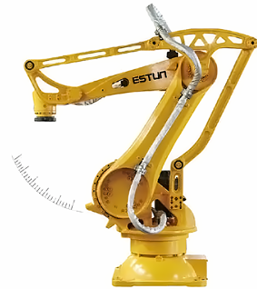
5-Axis Articulated Robots
5-axis articulated robots have one less wrist rotation axis compared to 6-axis (usually missing the A6 axis tool rotation axis), resulting in lower cost but slightly reduced flexibility. They are mainly used for spraying, simple welding, and handling applications that do not require complex wrist movements.
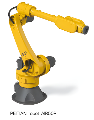
6-Axis Articulated Robots
6-axis articulated robots have complete 6 degrees of freedom:
-
A1 base rotation ±180°
-
A2 arm pitch -60°+85°
-
A3 forearm pitch -120°+120°
-
A4 wrist rotation ±180°
-
A5 wrist swing ±120°
-
A6 tool rotation ±360°
They have the highest flexibility and can achieve arbitrary positions and orientations. They are the mainstream choice for vision-guided applications, capable of adapting to various grasping angles and supporting complex trajectory planning. They are mainly used for complex welding, precision assembly, grinding and polishing, material handling applications.
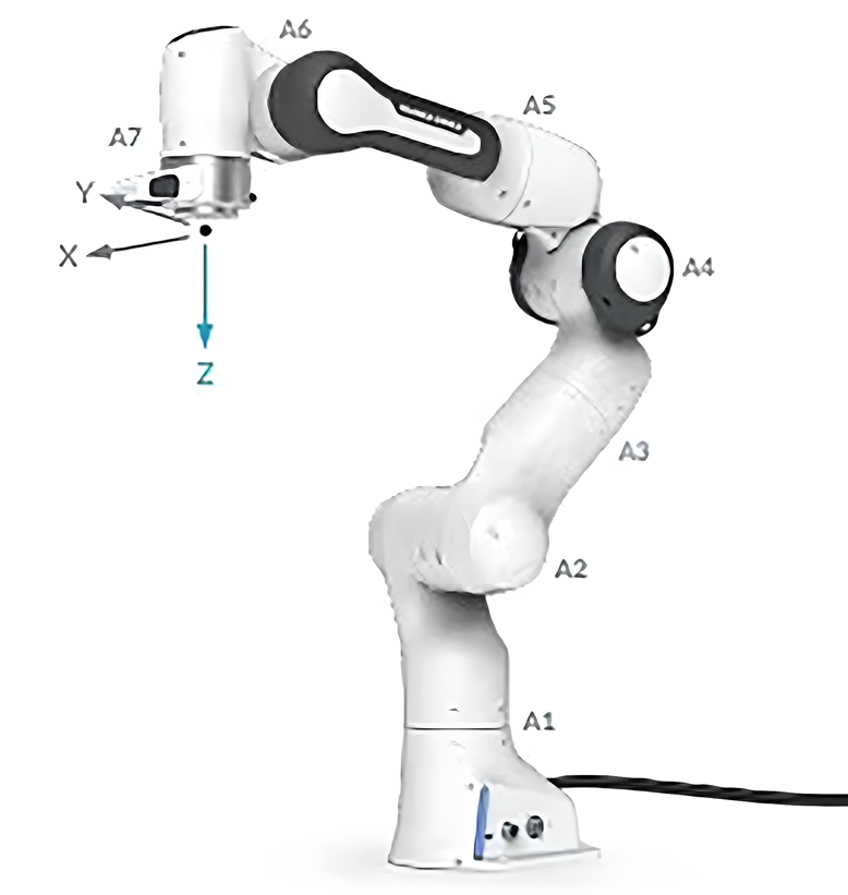
7-Axis Articulated Robots
7-axis articulated robots add one redundant axis (usually in the middle of the upper arm or forearm) to the 6-axis foundation. They can avoid obstacles and work more flexibly in confined spaces, but control is more complex. They are mainly used for aerospace assembly, confined space operations, and human-robot collaboration applications.
Cartesian Robots
Cartesian robots are based on Cartesian coordinate systems, consisting of mutually perpendicular linear motion axes, with all joints being prismatic joints.
Classification by Structural Scale
-
Standard Cartesian robots: Use linear modules or ball screw guide combinations, with working ranges typically within 2 meters. They have compact structure suitable for single machine operations, with repeatability reaching ±0.02mm, making them the most accurate among all robot types.
-
Gantry robots (portal robots): Use large steel structures or aluminum profiles as frameworks, with beam spans reaching over 40 meters. They can cover entire production lines or multiple equipment, typically configured with 2-4 axes (XZ, XYZ, XYZR).
Classification by Number of Axes
-
Single-axis robots: Single linear motion, such as electric slides.
-
Two-axis robots: XY plane or XZ vertical movement.
-
Three-axis robots: XYZ three-dimensional space movement, most common configuration.
-
Four-axis and above: Addition of rotation axes or additional linear axes.
The main characteristic of this robot type is that the workspace is rectangular, with the entire area effectively usable. Modular design makes them easy to expand and customize, particularly suitable for large span applications. Limitations include only linear motion capability, lack of rotation ability, large footprint, and poor flexibility.
In vision-guided applications, they have advantages of simple programming and regular workspace. They are mainly used for CNC machine tool loading/unloading, 3D printing, precision assembly, dispensing and coating, laser cutting, inspection equipment, logistics sorting, and applications requiring high-precision positioning and regular stacking/destacking.
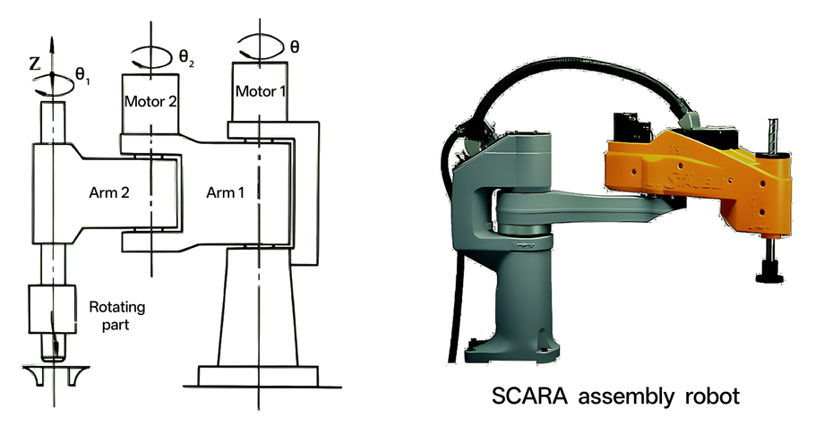
SCARA Robots
SCARA (Selective Compliance Assembly Robot Arm) is specifically designed for assembly operations, using a 4-axis configuration (3 rotary joints plus 1 linear joint) with dual-arm parallel joint structure. Its unique feature is horizontal compliance while maintaining vertical rigidity, giving it unique advantages in assembly operations.
4-axis articulated robots typically adopt SCARA structure or specialized palletizing configuration, with 3 rotation axes and 1 vertical movement axis. They have high speed and high precision in horizontal planes, mainly used for palletizing operations, simple assembly, and loading/unloading applications. They feature fast movement speed, high precision, and moderate cost, mainly used in electronics manufacturing. For example, FANUC’s SR series SCARA robots are widely used in electronic assembly lines, with arm reaches from 400mm to 650mm and payloads from 3kg to 6kg, mainly used for electronic assembly and high-speed pick-and-place operations on planes.
Parallel Robots (Delta)
7-axis articulated robots add one redundant axis (usually in the middle of the upper arm or forearm) to the 6-axis foundation. They can avoid obstacles and work more flexibly in confined spaces, but control is more complex. They are mainly used for aerospace assembly, confined space operations, and human-robot collaboration applications. Parallel robots adopt closed-loop kinematic chain structures, where the end effector is connected to the base through at least two independent kinematic chains. Delta robots are the most typical representatives, with three or four parallel arms simultaneously controlling the end effector, forming an inverted cone-shaped workspace with all actuators located at the base, making moving parts extremely lightweight.
Core advantages include fastest speed (up to 10m/s), acceleration up to 100m/s², high precision and good repeatability (±0.1mm), high stiffness, small cumulative errors, and excellent dynamic performance. Limitations include limited load capacity (typically less than 5kg) and relatively small workspace. They are mainly used for high-speed light-load pick-and-place applications such as food packaging, electronic product sorting, and pharmaceutical industry packaging.
Classification by Coordinate System
Robot classification by coordinate system is mainly based on their kinematic characteristics and control complexity.
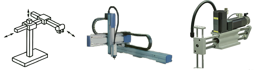
Cartesian Coordinate System (PPP)
Also called Cartesian coordinate system, based on three mutually perpendicular linear coordinate axes (X, Y, Z axes). The motion equations are simplest:
P(x,y,z) = (x₀±Δx, y₀±Δy, z₀±Δz)Each axis is independently controlled with no kinematic coupling. Programming is intuitive and simple, allowing direct reading of movement distances from coordinate axes. Changes in robot end effector spatial position are achieved through movement of three mutually perpendicular Cartesian coordinates x, y, z.
This system is most suitable for applications requiring high-precision linear positioning, such as wafer handling, precision machining, and large workpiece processing. It has the highest workspace utilization rate, with the entire rectangular area effectively usable, and motion decoupling makes control simple.
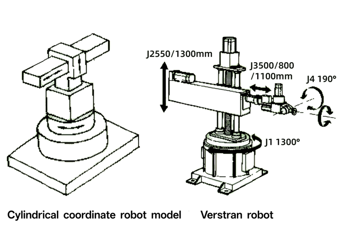
Cylindrical Coordinate System (RPP)
Also called cylindrical coordinate system, based on cylindrical coordinates (r, θ, z). The coordinate transformation relationship is:
x = r·cos(θ), y = r·sin(θ), z = zChanges in robot end effector spatial position are achieved through two translational coordinates and one rotational coordinate. A vertical column provides Z-axis up-down movement, horizontal arm performs radial movement, and base performs rotational movement.
This system balances complexity and practicality. Under the same workspace conditions, the body occupies less volume than Cartesian coordinate types. It is mainly used for confined space operations, cylindrical workpiece machining, and pipe welding applications. Motion coupling is relatively weak, control is relatively simple, and motion flexibility is moderate.
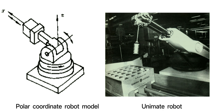
Spherical Coordinate System (RRP)
Also called polar coordinate system, based on spherical coordinates (r, θ, φ). Coordinate transformation is more complex:
x = r·sin(φ)·cos(θ), y = r·sin(φ)·sin(θ), z = r·cos(φ)Robot arm movement consists of one linear motion and two rotational motions: extension along x-axis, pitch around y-axis, and rotation around z-axis. It can grasp workpieces on the ground or at lower positions, has longer arm reach and large coverage area, but programming is relatively complex requiring coordinate transformation, and position errors are proportional to arm length.
It is mainly used in traditional industrial fields such as injection molding, spot welding, and arc welding. Motion coupling is strong, control is complex, motion flexibility is good, and it occupies relatively small space.
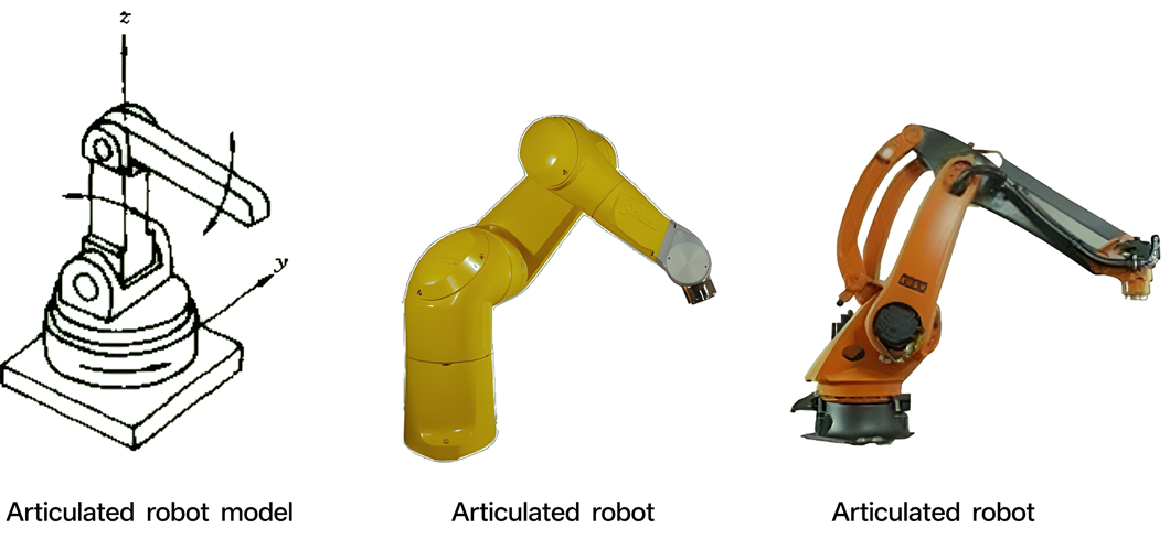
Joint Coordinate System (RRR)
Also called rotary coordinate system, based on serial structures of multiple rotary joints, divided into vertical joint coordinates and planar (horizontal) joint coordinates. It requires complex forward and inverse kinematic calculations. Typical configuration has 6 rotary joints forming complex irregular spherical workspace.
It has the highest degree of kinematic coupling, requiring advanced control algorithms, and can provide maximum motion flexibility for complex three-dimensional trajectories. It is mainly used for welding, spraying, assembly, and various other applications. Motion coupling is strong, control is most complex, motion flexibility is best, and it occupies the smallest space.
Classification by Drive Method
Electric Drive
Electric drive uses AC servo motors, DC servo motors, or stepper motors, driving joints through precision reducers, timing belts, and other mechanical transmission mechanisms. Modern electric robots commonly use closed-loop control systems with fast and accurate response.
Technical advantages are significant. Repeatability can reach ±0.02mm, energy conversion efficiency is high (above 85%), working environment is clean, maintenance costs are low, operating noise is small (<70dB), and complex trajectories can be achieved through multi-axis coordinated control. FANUC’s M-2000 series electric robots have reached 2300kg load capacity, breaking traditional limitations of electric robot load capacity.
Main limitations include smaller output torque under the same weight, relatively high initial investment, but with technological development, they are replacing more and more hydraulic and pneumatic applications. They are suitable for most industrial applications, especially vision-guided applications requiring high precision and high speed.
Hydraulic Drive
Hydraulic drive utilizes liquid (usually hydraulic oil) pressure energy converted to mechanical energy. System pressure is typically 7-35MPa, with power density reaching above 7kW/kg. Core components include hydraulic pumps, hydraulic cylinders, hydraulic motors, servo valves, and accumulators. Electro-hydraulic servo systems can achieve precise control.
They are irreplaceable in heavy-load applications. Large output force (can provide enormous output force and torque, up to tens of thousands N·m), high power density (output power is 5-10 times that of electric systems under the same volume), smooth transmission (liquid incompressibility results in smooth motion without vibration), good explosion-proof properties (suitable for flammable and explosive environments), and responsive action (fast response speed, reaching millisecond level). However, they are sensitive to temperature and require cooling systems to maintain oil temperature.
Main limitations include large energy conversion losses (efficiency 60-80%), liquid leakage issues, large working noise (>80dB), requirement for complex oil circuit systems, and high maintenance costs. They are mainly used for large stamping lines, shipbuilding, heavy machinery manufacturing, forging equipment, and other applications with typical loads exceeding 500kg or even several tons.
Pneumatic Drive
Pneumatic drive uses compressed air (0.4-0.8MPa) to drive cylinders, pneumatic motors, vacuum suction cups, and other actuating elements. Systems have simple structures, mostly using open-loop control or simple closed-loop control, with air as working medium that is convenient and pollution-free.
Cost advantages are obvious. Simple structure (high standardization of components, easy maintenance), quick action (fast response speed, 20-50ms), low cost (both initial investment and operating costs are low), high safety (fireproof and explosion-proof, automatic stop on overload), clean and environmentally friendly (no pollution, suitable for food and pharmaceutical industries), and good compliance (air compressibility provides cushioning effect).
Main limitations include low positioning accuracy (±0.1-0.5mm), relatively small output force (generally less than 2000N), poor speed stability (affected by air pressure fluctuations), and difficulty achieving precise position and speed control. They are mainly used in electronic manufacturing, food industry, packaging industry, simple assembly, and other applications with low precision requirements, particularly suitable for "point-to-point" rapid movement operations.
Hybrid Drive
Hybrid drive systems combine advantages of different drive methods. Common combinations include electro-hydraulic hybrid (electric motor driving hydraulic pump) and electro-pneumatic hybrid (electric robot with pneumatic gripper).
Typical applications such as electric robots equipped with pneumatic grippers combine electric precision positioning with pneumatic quick clamping functions. This combination is widely used in automation production lines, ensuring both positioning accuracy and reducing gripper mechanism costs.
Vision-Guided Application Selection Guide
In 3D vision-guided grasping and depalletizing applications, robot selection requires comprehensive consideration of multiple factors.
Application Scenario Recommendations
| Application Type | Recommended Type | Load Range | Precision Requirement | Notes |
|---|---|---|---|---|
High-precision assembly |
6-axis articulated |
<20kg |
±0.05mm |
High flexibility requirement |
Planar pick-and-place |
SCARA |
<10kg |
±0.01mm |
Speed priority |
Heavy-load depalletizing |
6-axis articulated |
>100kg |
±0.2mm |
Force priority |
High-speed sorting |
Parallel robot |
<5kg |
±0.1mm |
Fastest speed |
Large span operations |
Cartesian |
<50kg |
±0.02mm |
Stable precision |
Flexible grasping |
Collaborative robot |
<35kg |
±0.1mm |
High safety |
Selection Principles
The following principles should be followed during selection:
-
Load matching: Robot rated load should be 1.2-1.5 times the actual load
-
Precision requirements: Select appropriate type based on application precision needs
-
Speed requirements: Consider production cycle requirements for speed
-
Workspace: Ensure workspace covers all operation points
-
Cost-effectiveness: Select the most economical solution while meeting functional requirements
|
In actual selection processes, comprehensive evaluation combined with specific application scenarios is recommended. |