Eye in hand - Six-axis robot
Preparation
-
Complete the connection of the camera, industrial computer, and robot hardware system.
-
Place the calibration board at the center of the range of motion on one side of the robot, and ensure that the position of the calibration plate remains unchanged during the entire calibration process.
-
Start the internal parameter check tool in Epic Eye to check the camera internal parameter accuracy.
-
Epic Pro configuration:
Open the project solution and enter the workspace to complete the following configuration:
-
Add a custom robot and enable communication configuration (if the communication configuration is not enabled, the robot pose data needs to be manually entered during the calibration process).
-
Add a camera, connect the camera and adjust the camera parameters to ensure that the calibration board in the 2D view is clear and the exposure is appropriate, and that the calibration board point cloud in the point cloud view is smooth.
-
Calibration process
Check the robot’s absolute locating accuracy
-
Enter the calibration process
In the camera, click Calibrate, select the Eye in hand camera installation method, and then click OK to enter the calibration process.
-
Check the robot’s absolute locating accuracy
-
Click Check the robot’s absolute locating accuracy.
-
Set the check type to "X Direction".
-
Click Start data; make sure the calibration board is in the camera’s field of view; click Obtain pose.
-
Click End data; use the teach pendant to move the robot, making sure it moves only a certain distance in the X direction and does not move in other directions; click Obtain pose.
-
Set the check type to the Y direction and Z direction respectively, and repeat steps c-d.
-
Click Calculate accuracy.
-
If the accuracy does not meet the requirements, it needs to re-check.
-
If the accuracy meets the requirements, click Return to perform the hand-eye calibration process.
-
-
Calibration process
-
Confirm the robot connection status
Epic ProContinuously check the connection status with the robot.
-
If the robot monitoring port status shows connected, the software can automatically obtain the robot pose data.
-
If shows not connected, it needs to check the robot pose displayed in the robot teach pendant and manually fill it in the point pair data.
-
-
Obtain point pair data
Move the calibration board to the center of the camera’s field of view, click Collect point pair data in the point pair list. A set of calibration board pose and robot pose in the current state, as well as the measurement accuracy are obtained.
When the measurement accuracy value is in the range of 0.997~1.003, it will be displayed in green, indicating that the current data is available; when it is in the range of 0.993~0.997 or 1.003~1.007, it will be displayed in yellow, indicating that the current data is at risk; when it is less than 0.993 or greater than 1.007, it will be displayed in red, indicating that the data is unavailable. It is recommended to delete the current data and re-collect. -
Adjust robot pose
After collecting the first set of point pair data, make sure the calibration board is in the camera’s field of view, and use the teach pendant to move the robot and adjust its pose so that each joint changes when moving, thereby driving the camera to change its pose around the calibration board.

-
Repeat collection of point pair data
After adjusting the calibration board pose, click Add to obtain the second set of point pair data. Repeat steps 3-4 to collect at least 10 sets of point pair data.
-
Calculate point pair data
Click Calculate current data to calculate all the point pair data collected above and obtain the hand-eye calibration results.
+ TIP: It is recommended to perform a calculation for each additional set of data after collecting four sets of point pair data.
-
View hand-eye calibration results
Click View calibration results to open the calculation result window and view the hand-eye calibration results.
Check the hand-eye calibration accuracy
-
Click Hand-eye calibration accuracy check.
-
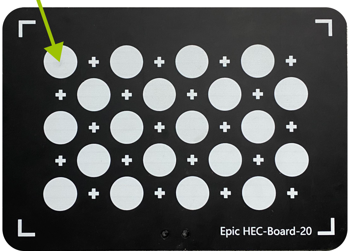
Click Obtain pose and send to robot to obtain the origin pose of calibration board.
The origin of the calibration board is located at the position indicated by the arrow in the figure below.
-
Move the robot to this position and check whether the robot end-effector coincides with the position of the calibration plate origin.