Epic Eye Laser L
Safety Instructions
Safety Statement
-
Before using this product, please read the product manual and fully understand the relevant safety information. Failure to follow the instructions may result in equipment damage, serious injury, or death.
-
Transfer assumes no legal responsibility for any personal injury, property loss, or other accidents caused by non-compliance with this manual or improper operation of the product.
Precautions
-
Avoid using the camera in environments with dust, strong electromagnetic interference, direct sunlight, or outside the specified temperature and humidity range.
-
Do not stare directly into the projection beam while the camera is operating to avoid eye injury.
-
Ensure the camera window is clean. Use a lint-free cloth to clean the window if necessary.
-
Do not perform installation, disassembly, or cleaning while the camera is powered on.
-
During transportation and installation, avoid severe impact or dropping of the camera.
-
If any abnormal conditions occur (e.g., unusual sounds, odors, or smoke), immediately cut off the power and perform an inspection.
-
Do not modify the camera or its power cables.
Packing List

Upon unboxing, check the camera and its accessories for any damage, rust, or deformation, and verify the completeness of the items against the packing list. If any damage or discrepancies are found, please contact Transfer.
Technical Specifications
Technical Parameters
System Parameters |
Baseline Length |
400mm |
Recommended Working Distance |
1200mm~3000mm |
|
Optimal Working Distance |
2100mm |
|
Near Field of View |
1260mm×1240mm@1.2m |
|
Far Field of View |
3220mm×2950mm@3.0m |
|
Z-Axis Accuracy |
0.15mm@2.4m |
|
Pixel Count |
3 million |
|
VDI/VDE Measurement Accuracy |
0.32@2.4m |
|
Resolution |
2048x1536 |
|
Accuracy Error |
<0.15% |
|
Typical Acquisition Time |
0.4s~0.9s |
|
Power Supply |
24V ⎓ 5A |
|
Peak Power |
40W |
|
Average Power Consumption |
22W |
|
Standby Power Consumption |
16W |
|
Hardware Parameters |
Dimensions (L*W*H) |
495mm×115mm×100mm |
Installation Method |
Fixed installation |
|
Communication Interface |
Gigabit Ethernet |
|
Light Source |
Blue (450nm) laser |
|
2D Camera |
Monochrome |
|
Environmental Parameters |
Operating Temperature |
-10℃~45℃ |
Operating Humidity |
20%~90% RH (non-condensing) |
|
Protection Level |
IP65 |
|
Cooling Method |
Passive |
|
Weight |
3.66kg |
|
Storage Temperature |
-20℃~70℃ |
|
Storage Humidity |
20%~90% RH (non-condensing) |
Subject to change without notice!


Installation and Connection
Camera Installation

|
Mounting the Camera on a Bracket

|
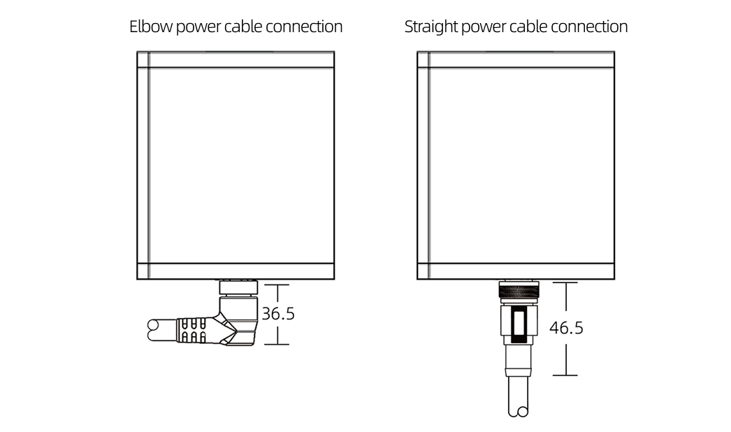
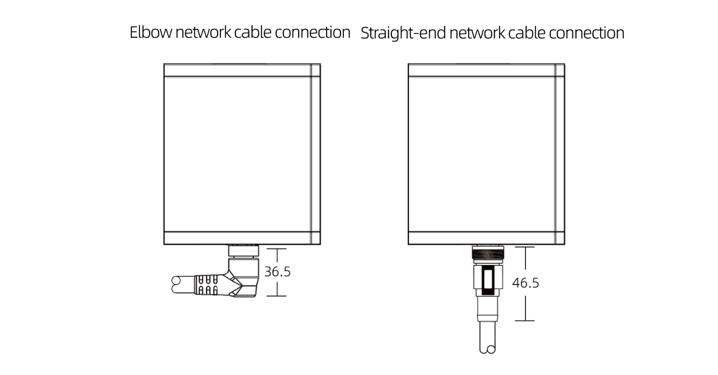
Cable Connection
Connection Guidelines
-
Do not plug or unplug cables while powered on. Connect all cables before turning on the power.
-
Align the plug with the socket and tighten slowly. Avoid excessive force.
-
Use cable ties to secure the camera network cable, power adapter, and power cord.
-
When connecting via a router, use the LAN port for all network cables.
-
For router or switch connections, use a gigabit router, switch, and dual-head RJ45 cable.
Connection Methods
-
Direct Connection between Camera and IPC

-
Industrial computer; 2.Camera network cable; 3.Camera; 4.M12-4Pin-15m power cable; 5.Rail power supply;6.Robot
-
-
Connection via Switch

1.Industrial computer; 2.Network cable; 3.Switch; 4.Camera network cable; 5.Camera; 6.M12-4Pin-15m power cable; 7.Rail power supply;8.Robot
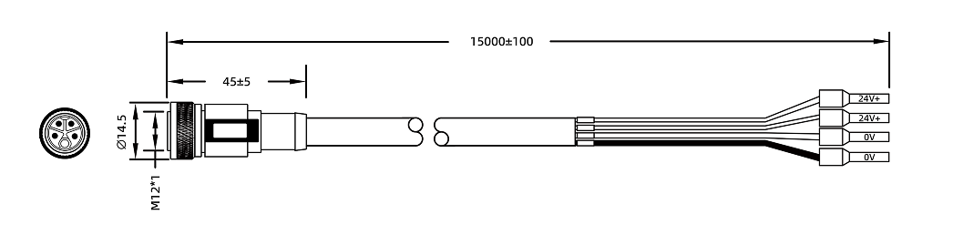
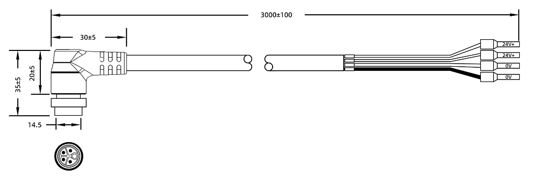
Power Cord Technical Specifications
Physical Parameters
Model |
Straight |
Angled |
CBL-PWR-12-15M CBL-PWR-12-30M |
CBL-PWR-12-15M-LU |
|
Color |
Black |
|
Outer Sheath Material |
PA |
|
Outer Diameter |
7.9(+0.25/-0.25)mm |
|
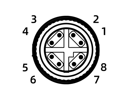
Connector |
M12, straight or angled, 4-pin loose wire end |
|
Conductor Diameter |
4*1.0mm² |
|
Static Bending Radius |
79 mm |
|
Dynamic Bending Radius |
90 mm |
|
EMI Shielding Performance |
Aluminum foil, metal braid, double shielding |
|
Safety |
RoHS compliant Flame retardant rating: VW-1 |
|
Cable Carrier Test |
Bending radius: 79 mm Stroke: 1000mm Speed: 2000 mm/s Cycles: ≥ 10 million |
|
Compatible Camera Models |
Laser L |
|

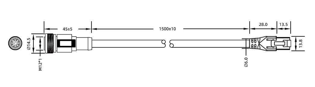
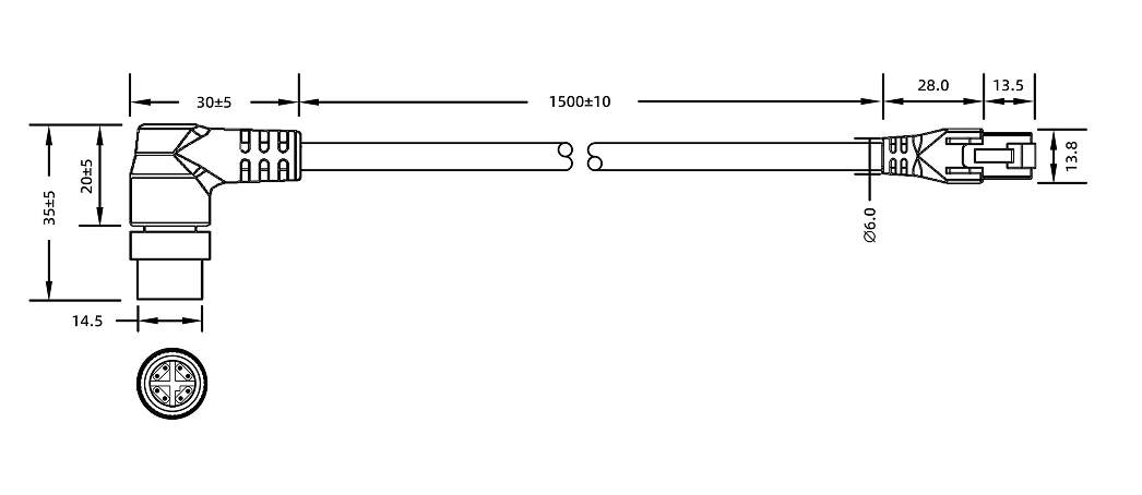
Network Cable Technical Specifications
Physical Parameters
Model |
Straight |
Angled |
CBL-ETH-12-15M CBL-ETH-12-30M |
CBL-ETH-12-15M-LU |
|
Color |
Black |
|
Outer Sheath Material |
PA |
|
Filler |
Cotton Thread |
|
Outer Diameter |
7.9(+0.25/-0.25)mm |
|
Connector |
M12, straight or angled, 4-pin loose wire end |
|
Conductor Diameter |
17AWG |
|
Static Bending Radius |
79 mm |
|
Dynamic Bending Radius |
90 mm |
|
EMI Shielding Performance |
Aluminum foil, metal braid, double shielding |
|
Safety |
RoHS compliant Flame retardant rating: VW-1 |
|
Cable Carrier Test |
Bending radius: 79mm Cycles: ≥ 10 million |
|
Compatible Camera Models |
Laser L |
|
Calibration Board Installation

|
Maintenance
To ensure stable operation and measurement accuracy, regular maintenance is essential to extend the device lifespan and detect potential issues early. Follow the prescribed maintenance tasks and keep records.
Daily Inspection
-
Check power status and connections regularly to ensure stable voltage output.
-
Monitor network stability and ensure data transmission speed meets requirements.
-
Maintain a suitable operating environment with proper ventilation for cooling.
-
Inspect camera integrity for signs of damage or corrosion.
-
Check cable connections for stress and signs of aging or cracking.
Regular Cleaning
Regularly clean the camera to keep lenses free from dust and stains. Use a soft, clean cloth with lens cleaner or glass cleaner to wipe the lenses.
Precautions
-
Disconnect the power before maintenance to avoid laser radiation.
-
Do not use alcohol or corrosive cleaning agents.
Technical Support Channel
For technical support, please call the official hotline at 4000-191-161 and follow the voice prompts to press 3 to enter the technical support channel.
Legal and Compliance


Disclaimer
Transfer assumes no responsibility for accidents caused by non-compliance or unauthorized modifications.