Operation guide
Adjust the view
-
Rotate the view: hold down the left mouse button and drag in any direction.
-
Pan the view: hold down the right mouse button and drag in any direction.
-
Zoom the view: scroll the mouse wheel.
-
Switch the 3D coordinate system perspective: click X/-X/Y/-Y/Z/-Z.
Edit point cloud
Crop point cloud
Follow steps to crop the point cloud:
-
Click
 on the toolbar.
 -
Select point cloud
Use the left mouse button to select the area to be cropped or retained in the 3D editing area, and right-click to complete the selection. In addition, move the mouse to the anchor point, hold down the left mouse button and drag in any direction to adjust the selection box.
-
Finish editing
-
If you need to crop the selected part, click Keep outside and then click Finish.
-
If you need to crop the area outside the selected part, click Keep inside and then click Finish.
-
In addition, if you need to reselect, click Cancel.
Point cloud downsampling
Follow steps to downsample the point cloud:
-
Click
 on the toolbar.
 -
Select the sampling method and set the sampling interval in the pop-up window, then click OK.
Sampling
Description
Uniform downsampling
Select points in the point cloud at a fixed step size, which is simple but may ignore important features.
Spatial downsampling
Select points according to their spatial distribution, which can better preserve spatial structural information.
Voxel downsampling
Divide the point cloud into voxel grids, retain a representative point in each voxel, reduce the number of points but may lose details.
Random downsampling
Randomly select points in the point cloud, simple and efficient but unstable results.
Standard downsampling
Use statistical methods to select representative points in the point cloud, retain structural features but high computational complexity.
If you are not satisfied with the point cloud effect after downsampling, you can retrace the point cloud operation.
Extract edge point cloud
For scenes that require edge matching, Follow steps to extract edge point cloud:
-
Click
 on the toolbar.
 -
After setting the following parameters in the pop-up window, click OK.
Parameter
Description
Edge angle threshold
The edge angle threshold determines the sensitivity of edge detection. A smaller threshold will result in more edge points being detected, possibly including some noise; a larger threshold may miss some actual edge points.
Nearest neighbor search method
KNN
A smaller nearest neighbor search radius may lead to unstable calculations, while a larger nearest neighbor search radius may lead to loss of local details.
RADIUS
The number of nearest neighbors to search needs to be adjusted according to the density of the point cloud. In dense point cloud data, a smaller number of nearest neighbors can be used, and in sparse point cloud data, a larger number of nearest neighbors can be used.
Adjust edge normal
Make the normal of the edge point cloud perpendicular to the edge and outward.
If you are not satisfied with the point cloud effect after edge extraction, you can retrace the point cloud operation.
Edit grab point
Add grab point
Follow steps to directly add grab points and adjust the grab point pose:
-
Click
 . The grab point is located at the center of the point cloud bounding box by default.
 -
Use the following two methods to adjust the grip point pose:
-
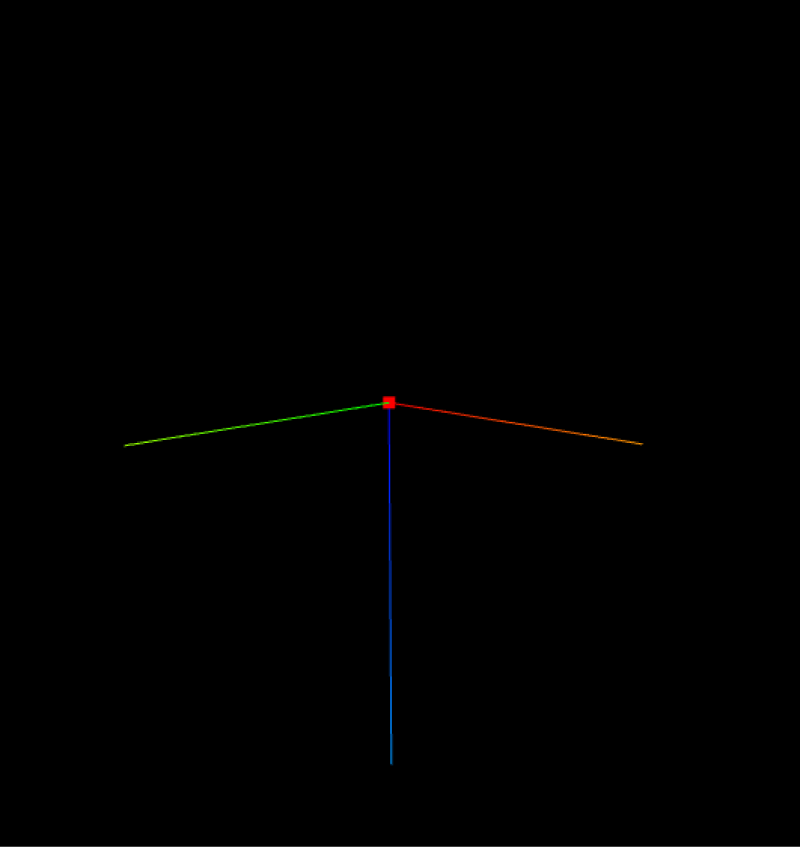
Rough adjustment: Click
 to display the grip point controller, move the mouse pointer to the coordinate axis of the controller, press and hold the left button and drag in any direction.
 -
Fine adjustment: In the grip point editing window, adjust the pose parameters.
-
Add teaching grab points
Teaching grab points refers to moving the robot end tool to the position when the workpiece is actually grasped, and recording this position as the grab point. Follow steps to add teaching grab points:
-
Use the teach pendant to control the robot so that its end tool moves to the position where the workpiece is actually grasped, and read and record the current tool pose.
-
Click
 to fill the posture value into the robot grab pose.
 -
Click OK, and the grip point will be added to the 3D editing area.
Mirror pickup point
According to the features of the workpiece and tool, the pickup point is mirrored in combination with specific rules to add multiple pickup points on the workpiece and increase the probability of successful pickup.
Operation instructions
Click the grab point to be mirrored in the grab point list, and then click ![]() on the toolbar to open the mirror grab point setting window. Complete the mirror setting in this window. The setting process is as follows:
on the toolbar to open the mirror grab point setting window. Complete the mirror setting in this window. The setting process is as follows:
-
Open mirror
Check Whether to open mirror.
-
Set axis vector
The axis vector is the axis of the three-dimensional coordinate axis of the mirror origin that is used as the reference for mirroring.
-
Grab point X/Y/Z axis
Grab point
Axis vector is X axis mirror
Axis vector is Y axis mirror
Axis vector is Z axis mirror
-
Custom: By setting the X axis, Y axis, and Z axis vectors, define an axis and mirror it based on this axis
-
-
Set axial coordinates
Axis coordinates refer to the origin based on which the mirror is made.
-
Grab point own coordinate system: that is, mirroring is based on the origin of the grab point itself.
-
Custom: Define an origin by setting the X-axis, Y-axis, and Z-axis parameter values, and mirror based on the origin.
-
-
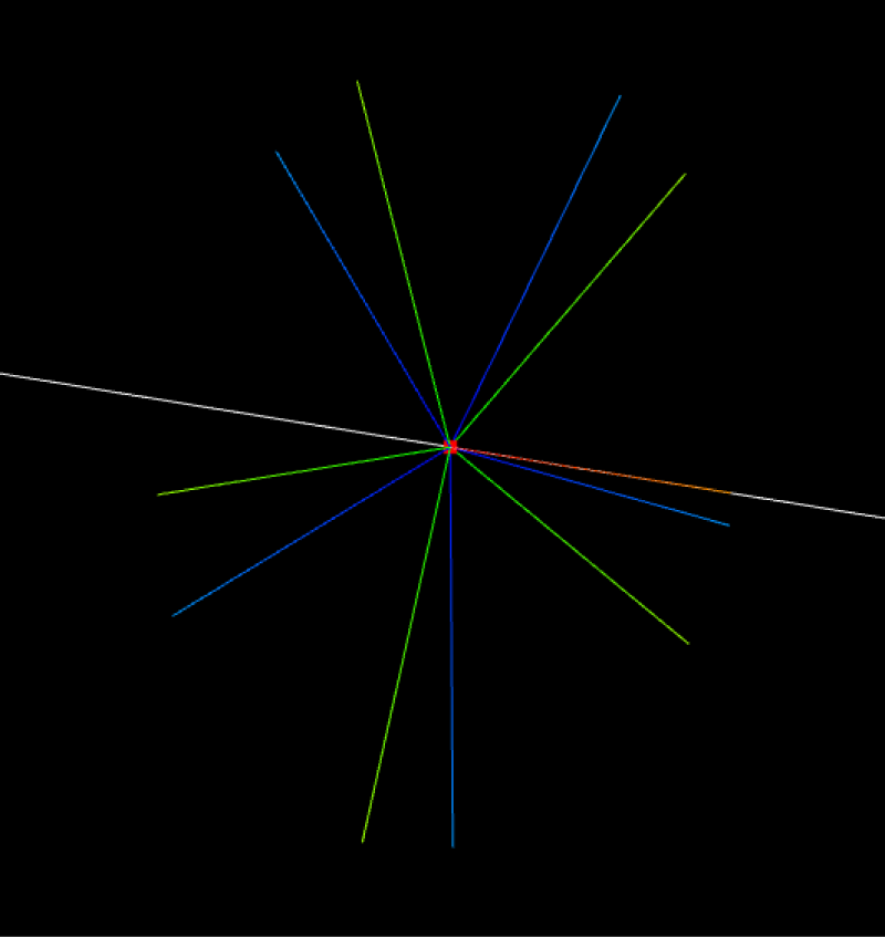
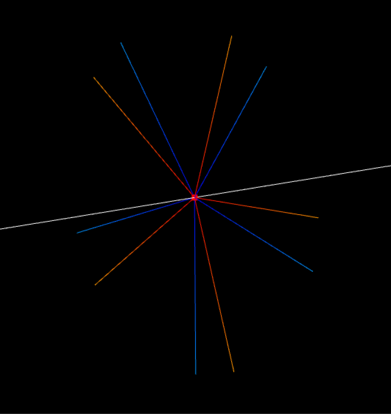
Set the number of mirror points
The number of mirror points is the final number of grab points.
-
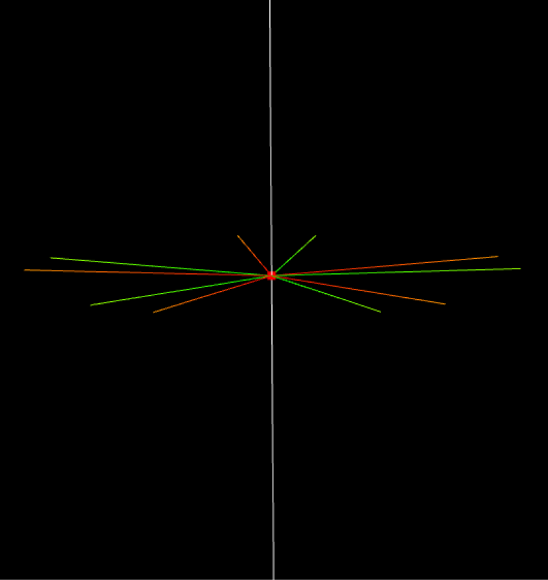
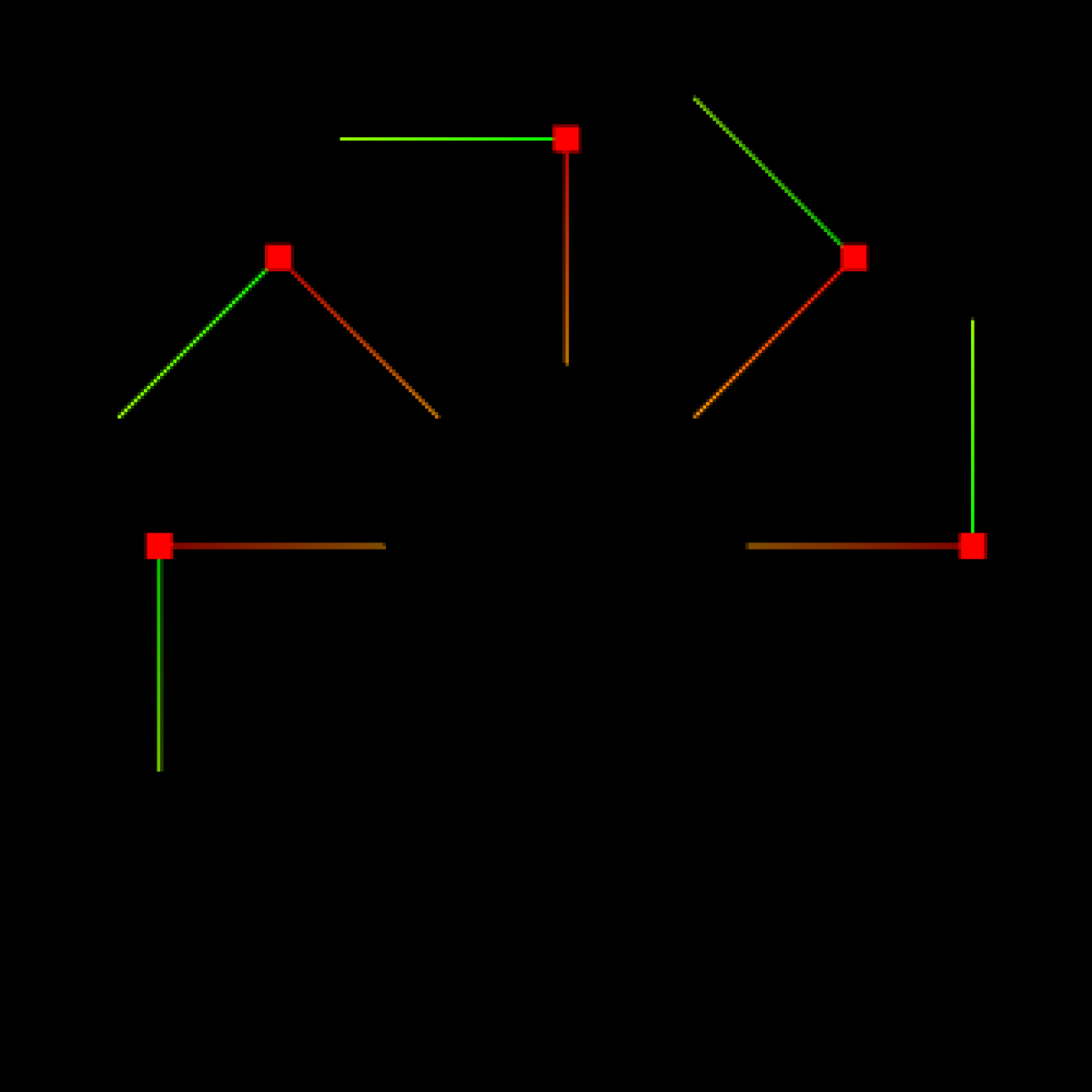
Set the mirror angle
The mirror angle is used to set the range of generated mirror points. The figure below shows the range of 0°-180°.
Hide the grab point
Click ![]() to the right of the corresponding grab point name in the grab point file list to hide it. Click again to unhide it.
to the right of the corresponding grab point name in the grab point file list to hide it. Click again to unhide it.
Edit the grab point name
Follow steps to edit the grab point name:
-
In the grab point file list, right-click the grab point name.
-
Click Edit name in the shortcut menu.
-
Enter a custom name in the pop-up window and click OK.
Copy grab point
In the grab point file list, right-click the grab point name and click Copy grab point in the shortcut menu.
Delete grab point
In the grab point file list, right-click the grab point name and click Delete in the shortcut menu.
Set grab point priority
For matching templates with multiple grab points added, the grab point priority determines the grab point that is tried first when grabbing. 0 represents the highest priority, 1 represents the second, and so on.
Perform the following steps to set the grab point priority:
-
In the grab point file list, right-click the grab point name.
-
Click Set priority in the shortcut menu that pops up.
-
In the pop-up window, set the priority and click OK.