Path Planning Parameters Description
Motion Planner
What is a Motion Planner?
A planner is a tool or algorithm used for path planning, which is used to find a feasible path from the starting point to the end point in a given space.
Planner Type
Select a planner in the drop-down list on the right. The motion planner has the following options:
Joint space planner
The joint space planner performs path planning directly in the joint space of the robot. Main features include:
-
Precise control: Suitable for precise control of robot joints.
-
Complexity: In high-dimensional joint space, the search may be complex.
-
Applicability: Suitable for applications that require precise joint motion, such as robot arms.
Linear planner
Linear planners plan paths along straight lines and are usually used for simple linear motion. Main features include:
-
Simple and fast: Suitable for simple environments and fast calculation speed.
-
Path straight: The generated path is a straight line, suitable for environments without obstacles.
-
Limitations: Not suitable for path planning in complex environments.
Bezier curve planner
Bezier Curve Planner uses Bezier curves to generate smooth paths. Main features include:
-
Smooth path: The generated path is smooth, suitable for applications that require path smoothness.
-
Complex calculation: The calculation complexity is high, suitable for precise control and environments that require smooth paths.
-
Flexibility: Able to generate curved paths of various shapes.
Fast random tree planner
Fast Random Tree is a path planner that gradually expands a tree structure through random sampling. It is particularly suitable for path search problems in high-dimensional space. The main features include:
-
Efficient exploration: It can quickly cover a large range of search space.
-
Simple implementation: The algorithm implementation is relatively simple.
-
Randomness: The path is unstable and the results may be different each time it is run.
Maximum number of attempts
The maximum number of iterations allowed by the planner when searching for a path. In order to prevent the planner from falling into an infinite loop, a maximum number of attempts needs to be set.
-
Higher value: Suitable for complex environments, it can increase the probability of finding a feasible path, but the calculation time will also increase.
-
Lower value: Suitable for simple environments, it can quickly end the search and save computing resources.
Sampling boundary compensation
The sampling boundary compensation refers to the distance that the boundary of the space cube between the starting point and the target point expands outward. The size of this expansion distance affects the range of the search space.
-
Larger value: When the compensation value is large, the boundary of the space cube expands outward more, and the search space becomes larger.
-
Smaller value: When the compensation value is smaller, the boundary of the space cube expands less outward and the search space becomes smaller.
Planning resolution
The size of each step when planning the path determines the precision of the search.
-
High resolution (small step): The generated path is more refined and smoother, but the amount of calculation increases.
-
Low resolution (large step): The calculation speed is faster, but the path may be rough and not smooth enough.
Maximum planning time
The maximum running time of the planner. If it exceeds this time, the planner will terminate the planning even if no path is found.
-
Longer time: Suitable for complex environments, increasing the probability of finding a feasible path.
-
Shorter time: Suitable for real-time applications, ensuring that the planner returns results within an acceptable time.
Whether to solve accurately
Whether the planner needs to find a path that fully satisfies all constraints.
-
Exact solution: Ensure that the path fully meets the constraints, but it may take longer.
-
Approximate solution: Allow the path to deviate from the constraints within a certain range, reduce calculation time, and improve efficiency.
Bezier curve planner parameters
Start point curvature
Start point curvature refers to the curvature value of the Bezier curve at the starting point in path planning. The start point curvature determines the degree of bending of the robot when it moves from the initial position. The larger the parameter value, the greater the bending degree.
Target point curvature
Target point curvature refers to the curvature value of the Bezier curve at the end point in path planning. The target point curvature determines the degree of bending of the robot when it approaches the target position. The larger the parameter value, the greater the bending degree.
Return pose type
The path point pose type output by the planner, and pose or joint angle can be chosen.
Retraction path planning
Type |
Description |
|---|---|
Do not plan the retraction path |
Only plans the path from the starting planning point to the pre-grasp point and checks for collisions at the grasp point. The number of path points is set by the interface, and no retraction grasp point check count is set. |
Collision detection of grabbing path |
Only plans the path from the starting planning point to the pre-grasp point, checking for collisions at the grasp point. The object to be grasped is added to the tool, and all path points are checked for collisions (purpose: treating the grasp path as the retraction path to perform collision detection with the grasped object on the retraction path). The retraction grasp point check count must be set, and the number of path points is set by the interface. |
Planning retraction path |
Plans the path from the starting planning point to the pre-grasp point, checking for collisions at the grasp point. The object to be grasped is added to the tool, then plans the path from the pre-grasp point back to the starting planning point. The number of path points is twice the amount set by the interface. |
Number of path points
Path points are the basic components of the trajectory, and each path point contains information such as position and direction. The number of path points affects the precision and accuracy of the trajectory. The more path points there are, the finer the trajectory is, but the planning time will also increase accordingly. For situations where the distance between the starting planning point and the grasping point is long, it is recommended to increase the number of path points; on the contrary, if the distance is short, the number of path points can be reduced.
|
Joint angle difference threshold
Joint angle difference refers to the sum of the absolute values of the difference between the robot’s joint angles at the previous path point and the next path point.
This parameter is used to limit the joint angle difference and avoid large changes in the robot’s posture during path planning, thereby making the path smoother.
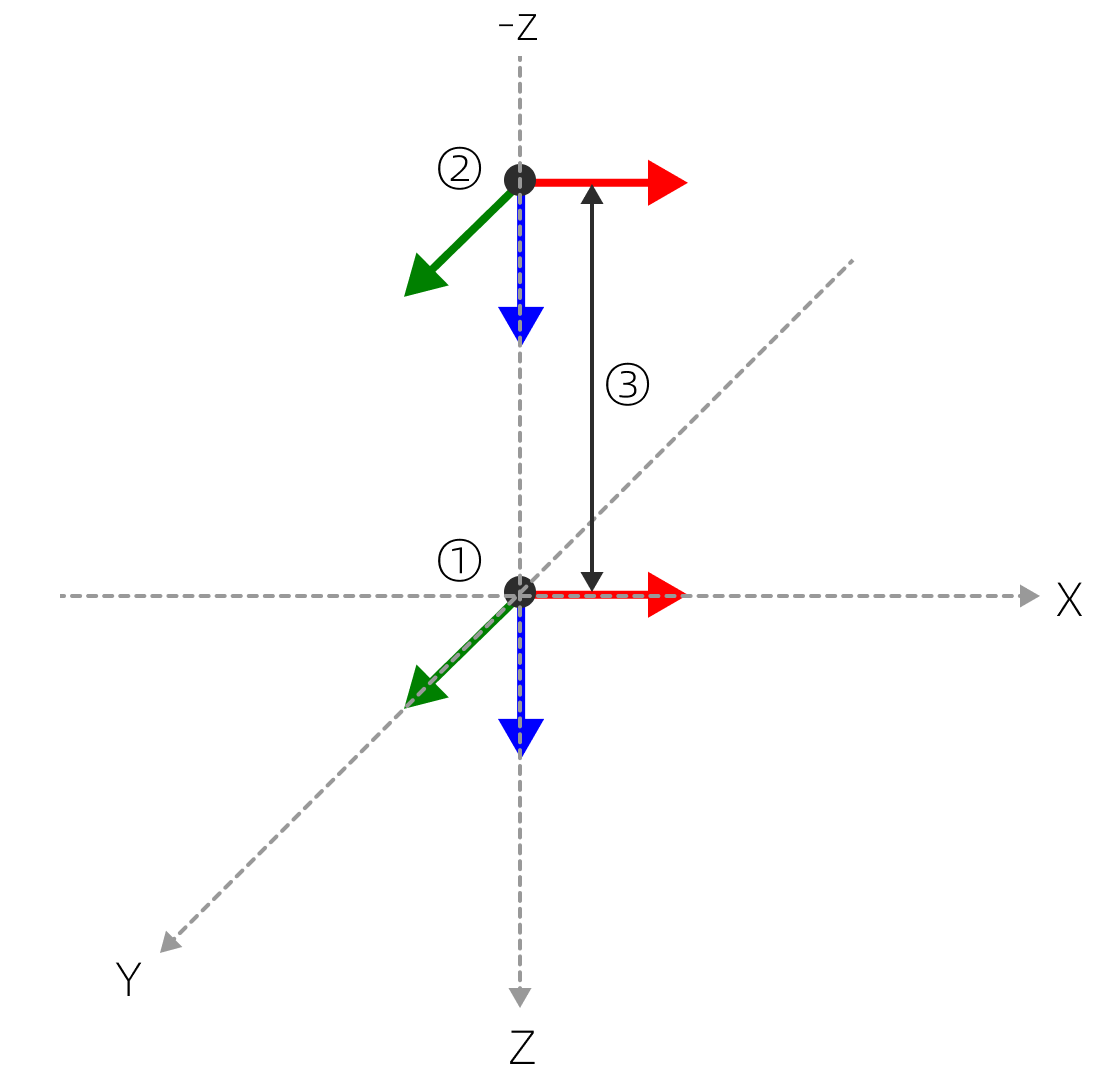
Pre-grab point offset distance
As shown in the figure below: ① grab point, ② pre-grab point, and ③ offset distance.
Grab point offset vector
X/Y/Z component setting instructions:
Parameter |
Description |
|---|---|
0 |
Do not offset in this direction. |
1 |
Offset in the positive direction. |
-1 |
Offset in the negative direction. |
The pre-grab point (②) shown in the figure above has X and Y set to 0 and Z set to -1.
Number of pre-grab point detections
Number of path points between the grab point and the pre-grab point.
Starting planning point
Add a path point based on the grasp point to plan a collision-free path.
Add start planning point
| The start planning point pose cannot be set directly through its own parameters, but needs to be achieved by setting the robot pose. |
-
In the robot entry, adjust the robot pose.
-
Click the + on the right side of the start planning point entry.
-
The starting planning point will be generated at the TCP and will be named "Starting Planning Point 1" by default.

Before starting planning point generation
After starting planning point generation
-
Set the start planning point model parameters (optional).
-
Click
 to the right of the starting planning point name.
 -
In the Set Starting Planning Point Attributes pop-up window, you can rename the starting planning point, edit its color, and set its size, opacity, and axis length.
-
In addition:
-
If need to adjust the planning point pose, you have to adjust the robot pose in the robot entry first, and then click Update planning point pose.
-
If the robot pose changes, click Move robot to this point to return the robot model to the robot planning point.