Epic Eye Log L
Safety Notice
Safety Statement
-
Before using this product, please read the product manual and correctly understand the safety information. Failure to comply with the safety instructions may result in equipment damage or serious injury or death.
-
Transfer will not be liable for any legal responsibility for personal safety accidents or property losses caused by non-compliance with this manual or improper operation of the product.
Precautions
-
Avoid using this camera in dusty environments, areas with strong electromagnetic interference, direct strong light, or environments outside the applicable temperature and humidity range.
-
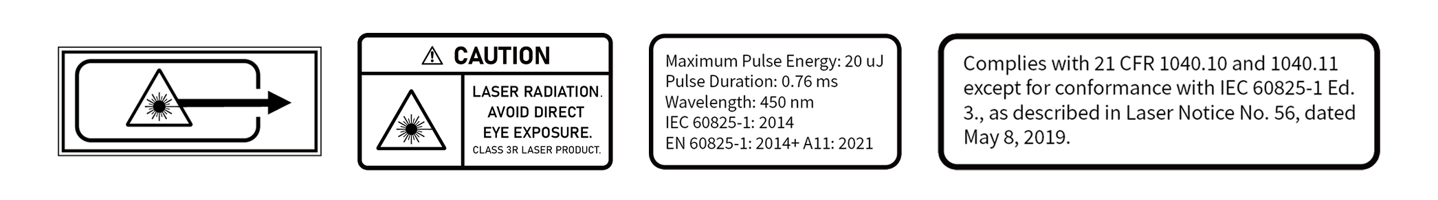
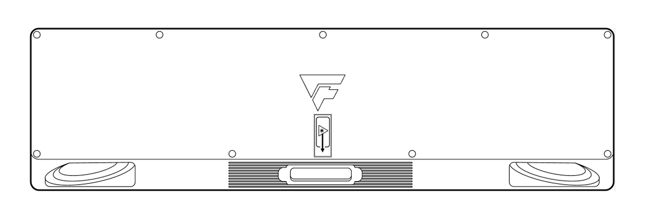
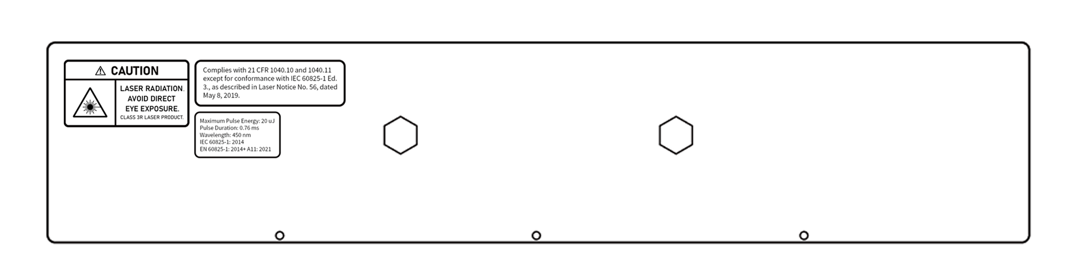
Do not directly stare at the projection beam during camera operation to avoid eye damage.
-
Ensure the camera window is clean. If cleaning is needed, please use a lint-free cloth.
-
It is strictly prohibited to install, disassemble, or clean the camera while it is powered on.
-
Avoid severe collisions or drops during transportation and installation.
-
If any abnormal conditions are found (such as abnormal sounds, odors, smoke, etc.), immediately cut off the power supply and conduct an inspection.
-
It is strictly prohibited to modify the camera and its power cord.
Package Contents
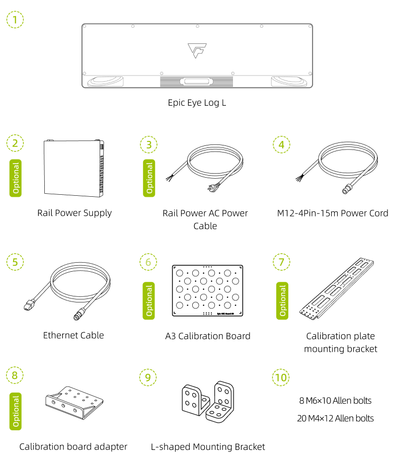
When unpacking, please check whether the camera and its accessories have any damage, rust, or impact marks, and verify that all materials are complete according to the package contents list. If the camera and its accessories are found to have damage, rust, or impact marks, or if the actual materials do not match the package contents list, please contact Transfer.
Technical Specifications
Technical Parameters
System Parameters |
Baseline Length |
400mm |
Recommended Working Distance |
1200mm~3500mm |
|
Optimal Working Distance |
2400mm |
|
Near Field of View |
1120mm×1030mm@1.2m |
|
Far Field of View |
3300mm×3160mm@3.5m |
|
Z-axis Accuracy |
0.15mm@2.4m |
|
Pixel Count |
2 Megapixels |
|
VDI/VDE Measurement Accuracy |
0.43@2.4m |
|
Resolution |
1420×1420 |
|
Accuracy Error |
<0.15% |
|
Typical Acquisition Time |
0.4s~1.4s |
|
Power Supply |
24V ⎓ 5A |
|
Peak Power |
34W |
|
Average Power Consumption |
16W |
|
Standby Power Consumption |
12W |
|
Hardware Parameters |
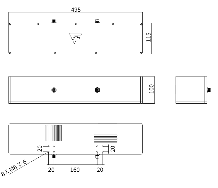
Dimensions (L*W*H) |
495mm×115mm×100mm |
Installation Method |
Fixed Installation |
|
Communication Interface |
Gigabit Ethernet |
|
Light Source |
Blue (450nm) Laser |
|
2D Camera |
Monochrome |
|
Smart Camera Specifications(1) |
Memory |
16G |
Storage |
128G |
|
Computing Units |
CPU, GPU, NPU |
|
Environmental Parameters |
Operating Temperature Range |
0℃~50℃ |
Operating Humidity |
20%~90% RH Non-condensing |
|
Protection Rating |
IP65 |
|
Cooling Method |
Passive |
|
Weight |
3.77kg |
|
Storage Temperature |
-20℃~70℃ |
|
Storage Humidity |
20%~90% RH Non-condensing |
(1): These specifications apply to smart camera products only.
If the parameter content in this manual is updated, no separate notice will be given. Please refer to the latest published data.
Installation and Connection
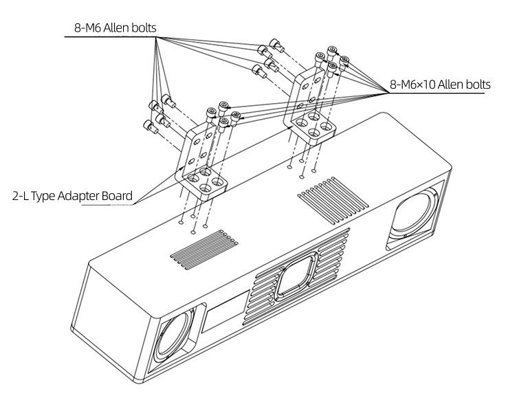
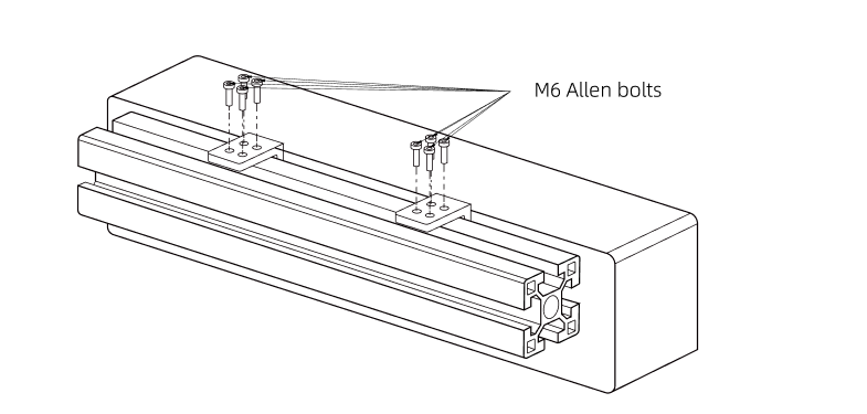
Installing the Camera
|
Installing Camera to Bracket
|
Connecting Cables
Connection Notes
-
Do not plug or unplug while powered on. Ensure all cables are connected before finally turning on the power.
-
Align the plug with the socket and tighten slowly. Do not forcefully twist or pull.
-
It is recommended to use cable ties to secure the camera network cable, power adapter, and power cord.
-
When using a router for connection, insert all network cables into the router’s LAN ports.
-
When using a router or switch for connection, it is recommended to use a gigabit router, gigabit switch, and gigabit dual-head RJ45.
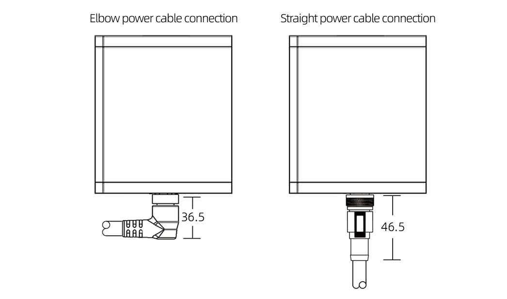
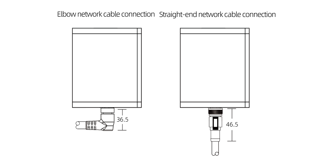
Connection Methods
-
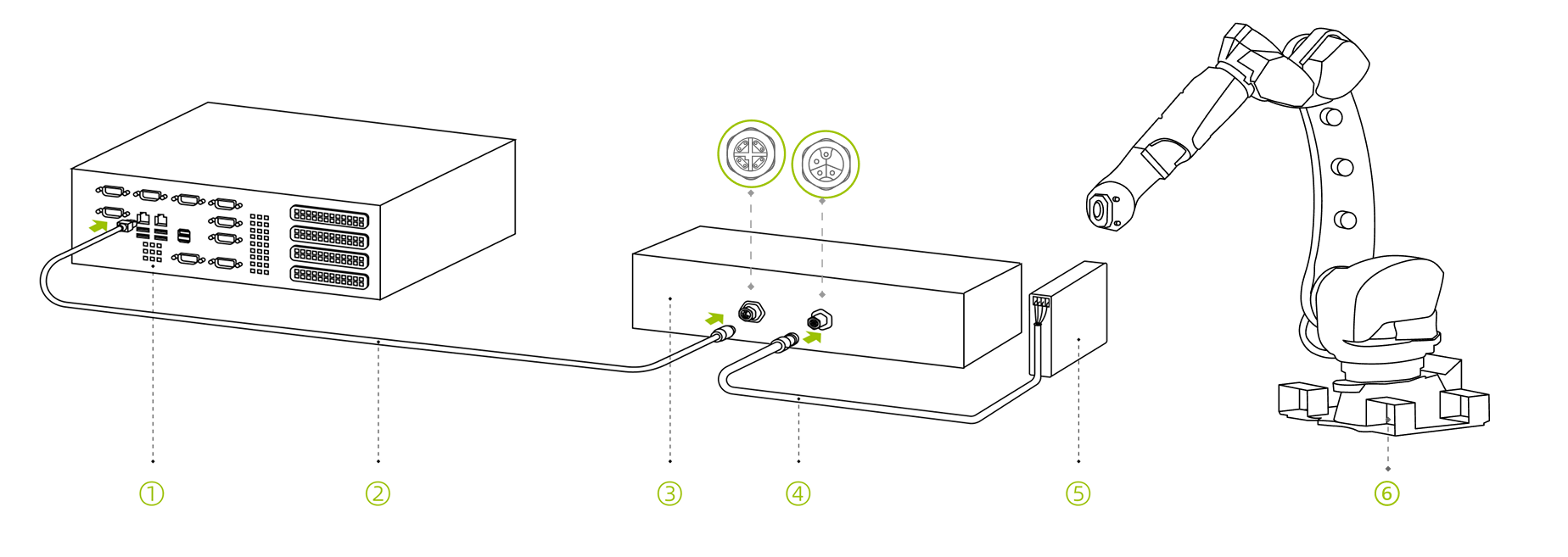
Direct connection between camera and industrial computer
-
Industrial computer; 2. Camera network cable; 3. Camera; 4. M12-4Pin-15m DC power cord; 5. Rail power supply; 6. Robot
-
-
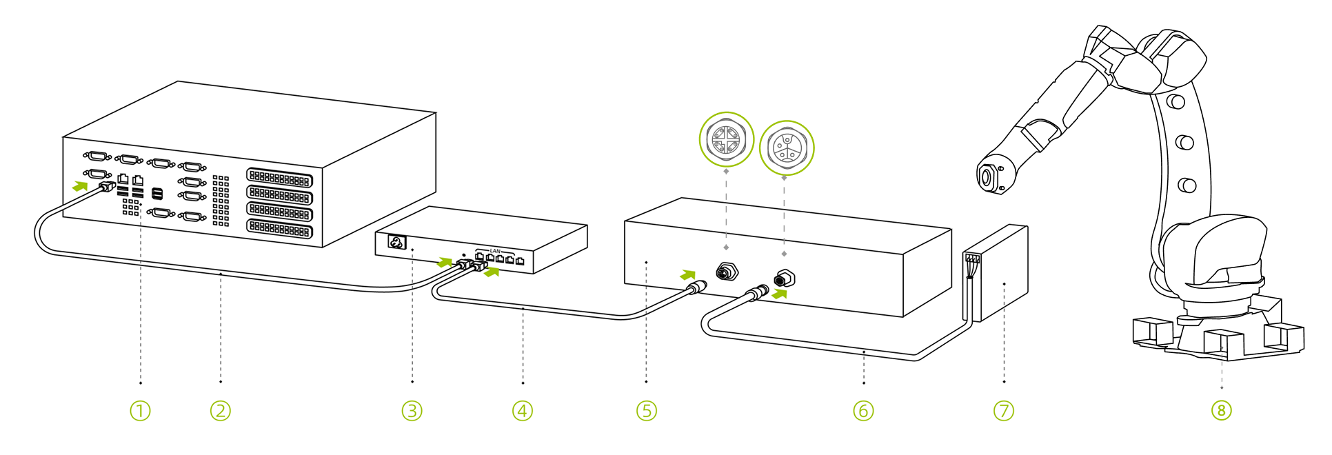
Camera connected to industrial computer through switch
-
Industrial computer; 2. Network cable; 3. Switch; 4. Camera network cable; 5. Camera; 6. M12-4Pin-15m DC power cord; 7. Rail power supply; 8. Robot
-
Smart Camera Connection Cable
Connection Notes
-
Prepare a display device that can be connected to the camera, such as an industrial PC or laptop.
-
Disconnect the display device after debugging.
Connection Methods
-
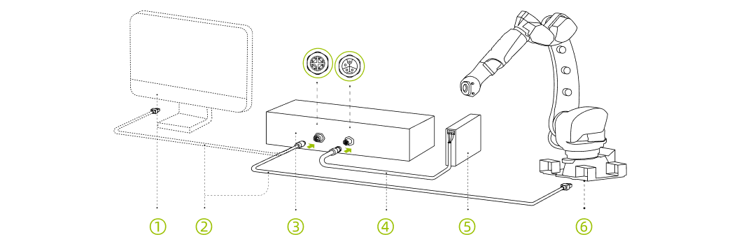
Direct Connection between Smart Camera and Robot
-
Display Device (Debug Connection); 2. Camera Network Cable; 3. Camera; 4. M8-4Pin-10m DC Power Cable; 5. Rail Power Supply; 6. Robot (Running Connection)
-
-
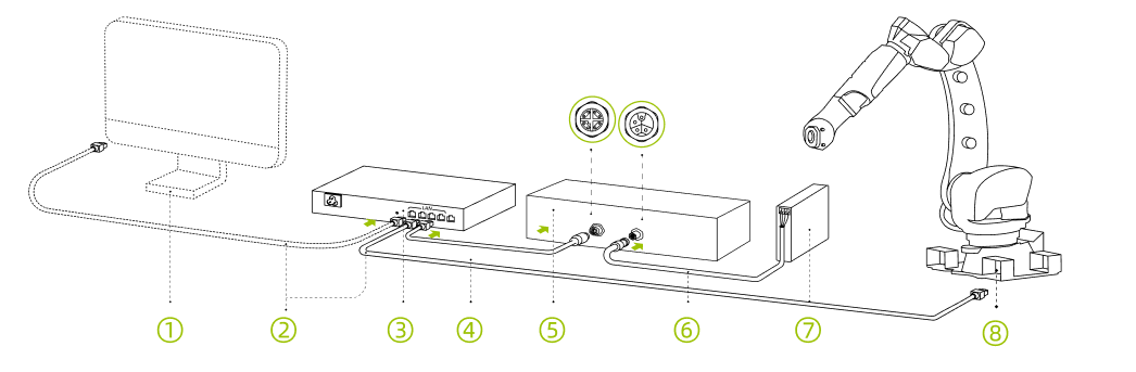
Connection between Smart Camera and Robot via Switch
-
Display Device (Debug Connection); 2. Network Cable; 3. Switch; 4. Camera Network Cable; 5. Camera; 6. M8-4Pin-10m DC Power Cable; 7. Rail Power Supply; 8. Robot
-
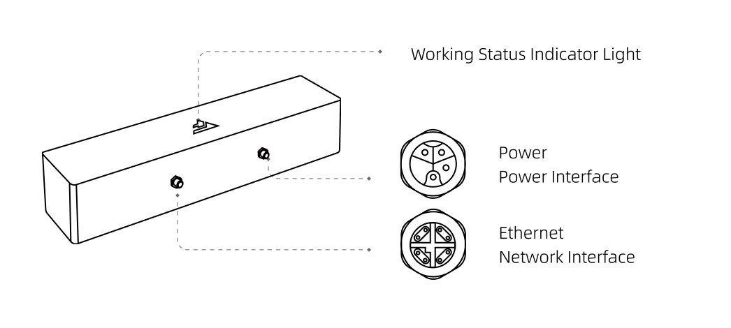
Grounding Instructions
-
Connect the camera’s grounding terminal to the robot’s grounding terminal.

-
Network Interface; 2. Power Line Interface; 3. Grounding Terminal;
-
Power Cord Technical Specifications
Physical Parameters
Model |
Straight |
Angled |
CBL-PWR-12-15M CBL-PWR-12-30M |
CBL-PWR-12-15M-LU CBL-PWR-12-30M-LU |
|
Color |
Black |
|
Outer Sheath Material |
PA |
|
Outer Diameter |
7.9(+0.25/-0.25)mm |
|
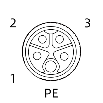
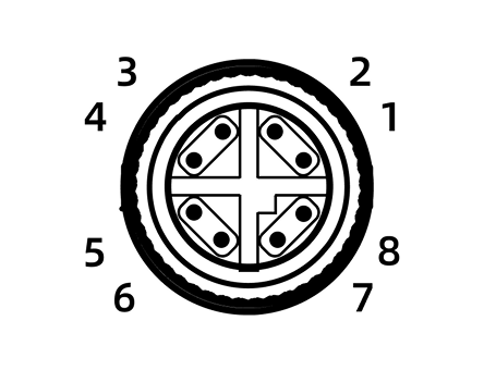
Connector |
M12, straight or angled, 4-pin loose wire end |
|
Conductor Diameter |
4*1.0mm² |
|
Static Bending Radius |
79 mm |
|
Dynamic Bending Radius |
90 mm |
|
EMI Shielding Performance |
Aluminum foil, metal braid, double shielding |
|
Safety |
RoHS compliant Flame retardant rating: VW-1 |
|
Cable Carrier Test |
Bending radius: 79 mm Stroke: 1000mm Speed: 2000 mm/s Cycles: ≥ 10 million |
|
Compatible Camera Models |
Laser L V2S Log L |
|
Dimensions
Unit: mm
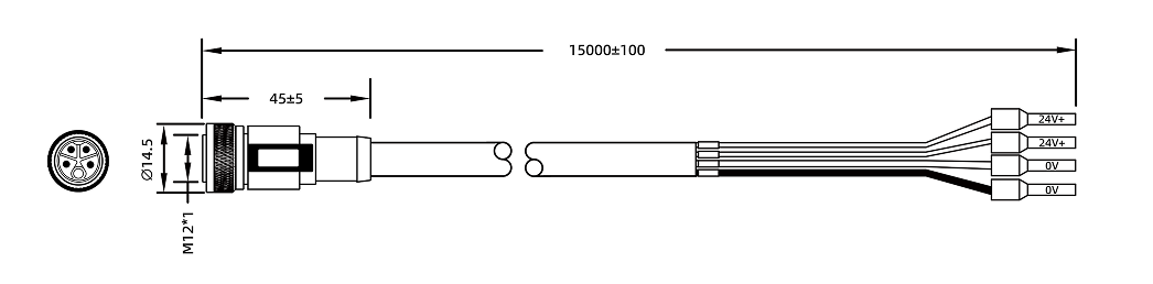
Model |
L |
|---|---|
CBL-PWR-12-15M |
15m |
CBL-PWR-12-30M |
30m |
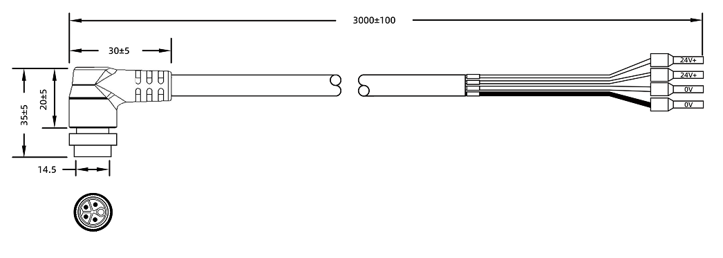
Model |
L |
|---|---|
CBL-PWR-12-15M-LU |
15m |
CBL-PWR-12-30M-LU |
30m |

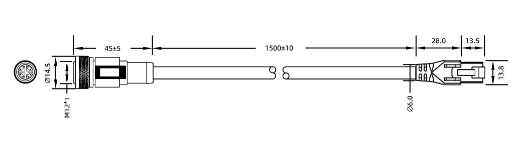
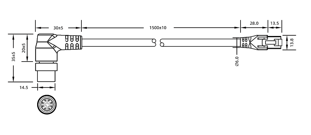
Network Cable Technical Specifications
Physical Parameters
Model |
Straight |
Angled |
CBL-ETH-12-15M CBL-ETH-12-30M |
CBL-ETH-12-15M-LU CBL-ETH-12-30M-LU |
|
Color |
Black |
|
Outer Sheath Material |
PA |
|
Filler |
Cotton Thread |
|
Outer Diameter |
7.9(+0.25/-0.25)mm |
|
Connector |
M12, straight or angled, 4-pin loose wire end |
|
Conductor Diameter |
17AWG |
|
Static Bending Radius |
79 mm |
|
Dynamic Bending Radius |
90 mm |
|
EMI Shielding Performance |
Aluminum foil, metal braid, double shielding |
|
Safety |
RoHS compliant Flame retardant rating: VW-1 |
|
Cable Carrier Test |
Bending radius: 79mm Cycles: ≥ 10 million |
|
Compatible Camera Models |
Laser L V2S Log L |
|
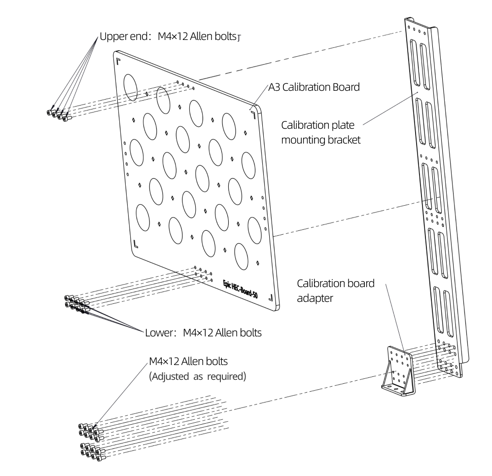
Calibration Board Installation
|
Maintenance
To ensure stable operation and measurement accuracy of industrial 3D camera hardware, regular maintenance is crucial. This not only extends equipment service life but also helps detect and prevent potential problems in time, reducing equipment failure rates and ensuring continuous stable operation of production lines. Please strictly follow the regulations for maintenance work and keep relevant records.
Daily Inspection
-
Check whether the power supply status is normal. Regularly check whether the power cord connector contact is good, ensure the power supply voltage output is stable and complies with power supply specifications. If necessary, it is recommended to use a UPS uninterruptible power supply to prevent unexpected power outages.
-
Check whether the network connection is stable and ensure the network transmission rate meets requirements.
-
Monitor whether the working environment temperature and humidity meet regulations. It is recommended to maintain good ventilation to ensure normal camera heat dissipation.
-
Check the integrity of the camera housing to ensure there are no abnormalities such as damage, deformation, or corrosion, and avoid risks of scraping or collision with environmental objects.
-
Check the tightness of camera installation and adapters to ensure there are no abnormalities such as deformation, loosening, or shaking.
-
Check the stress at cable connector locations, ensure cable routing is reasonable with no excessive bending, and the outer sheath shows no aging or cracking.
Regular Cleaning
Regularly clean the camera to ensure the lens is clean with no obvious dust or stains. Use a clean soft cloth to wipe the camera body, and use a clean, soft, lint-free cloth moistened with lens cleaner or glass cleaner to wipe the camera lens to avoid scratching the lens.
Precautions
-
The equipment must be powered off before maintenance to prevent laser radiation.
-
Do not use alcohol or other corrosive cleaning agents.
Storage and Transportation
-
Use original packaging or professional shockproof boxes for storing and transporting the camera.
-
Ensure storage environment temperature and humidity meet standards.
-
Avoid severe vibration and collision, and keep away from strong magnetic fields.
-
Maintain correct placement orientation and avoid direct strong light sources such as sunlight on the lens.
-
Before long-term storage, perform comprehensive cleaning first and conduct regular power-on inspections (every 3 months).
Fault Prevention and Repair
Fault Prevention
-
Establish equipment maintenance records and document all maintenance operations and abnormal conditions.
-
Regularly check camera internal parameter data and recalibrate when necessary.
Equipment Repair
It is strictly prohibited to disassemble or repair this equipment on your own to prevent laser radiation and equipment damage. If a fault occurs, please immediately contact Transfer technical support for factory repair. Transfer shall not bear any responsibility for equipment damage and accuracy degradation caused by any unauthorized disassembly or repair, and losses caused thereby shall be borne by the user.
Technical Support Channel
For technical support, please call the official service hotline 4000-191-161, and follow the voice prompt to press 3 to enter the technical support channel.
Legal and Compliance


Disclaimer
Transfer shall not bear any legal liability for personal safety accidents, property losses, etc. caused by users' failure to comply with safety regulations, improper operation of the camera, or unauthorized modification of the camera, power cord, etc.